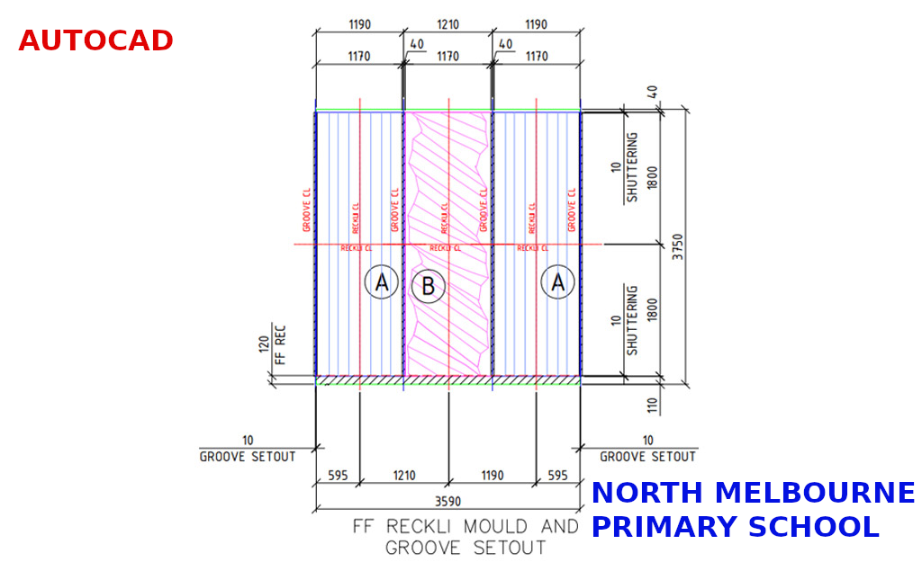
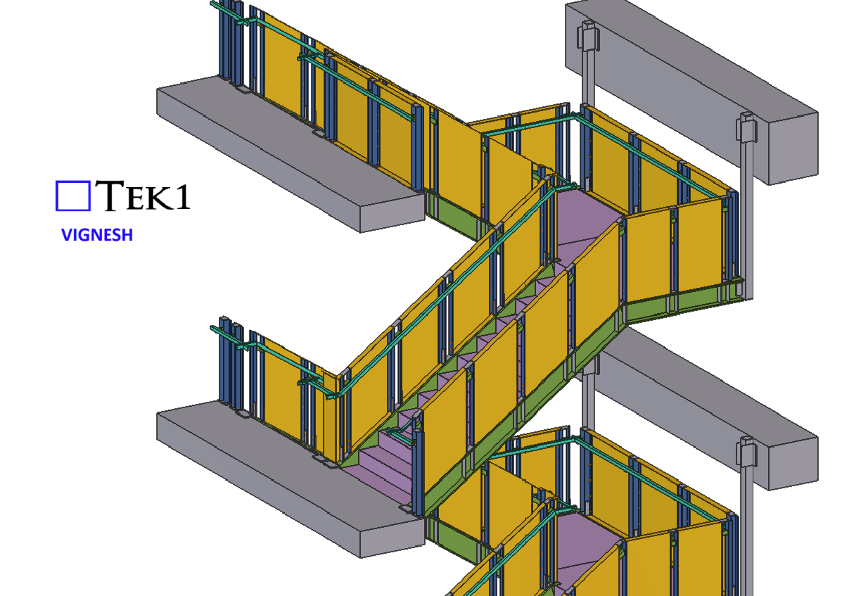
These details could be different for each job. Check the details provided by client. If missing ask. The detail Nos will be different. Use what is specific for the job
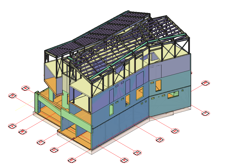
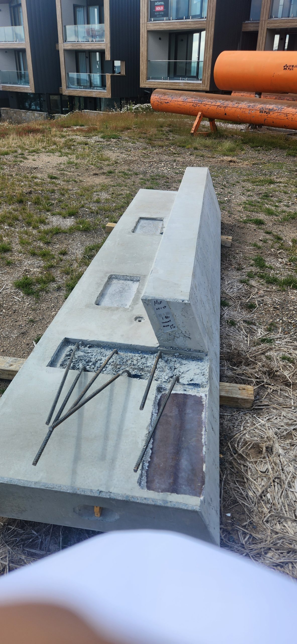
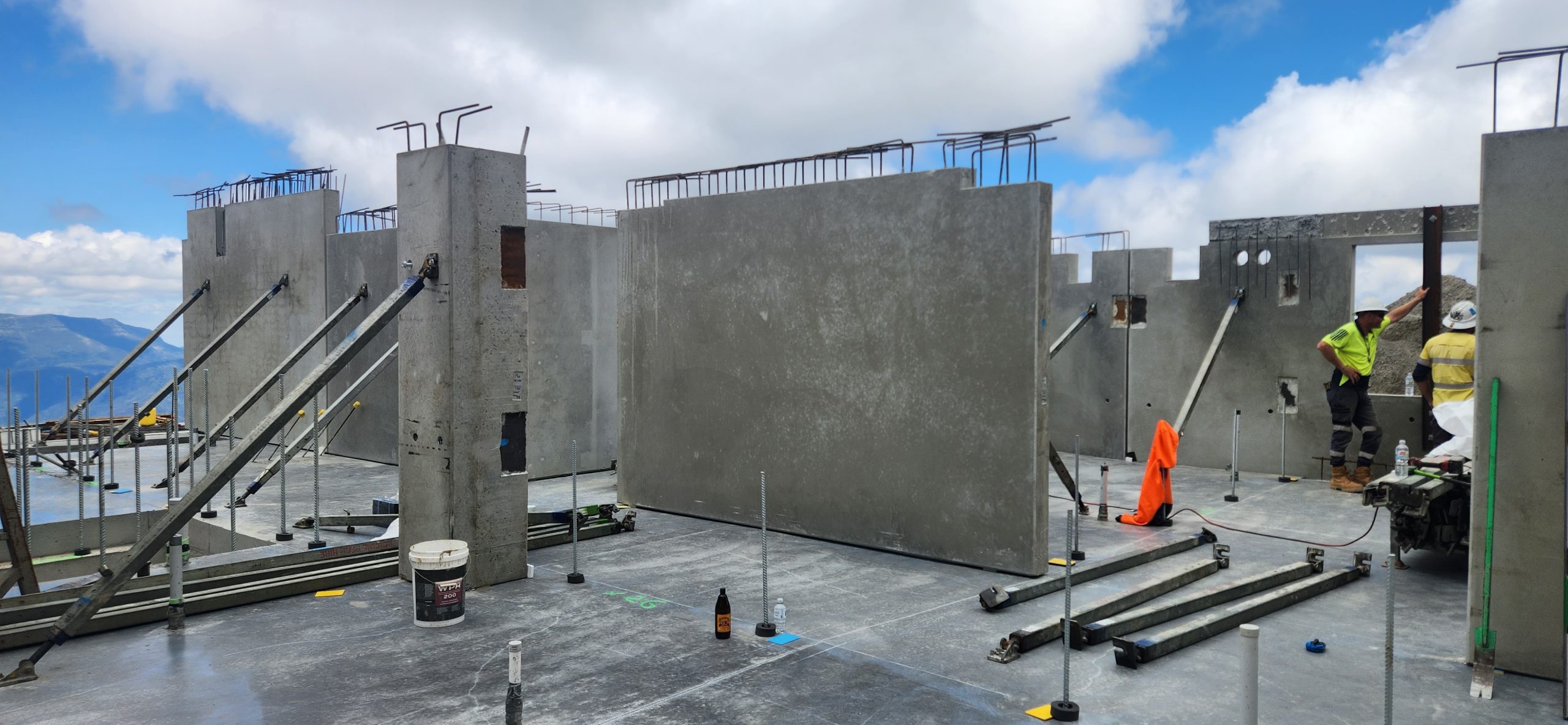
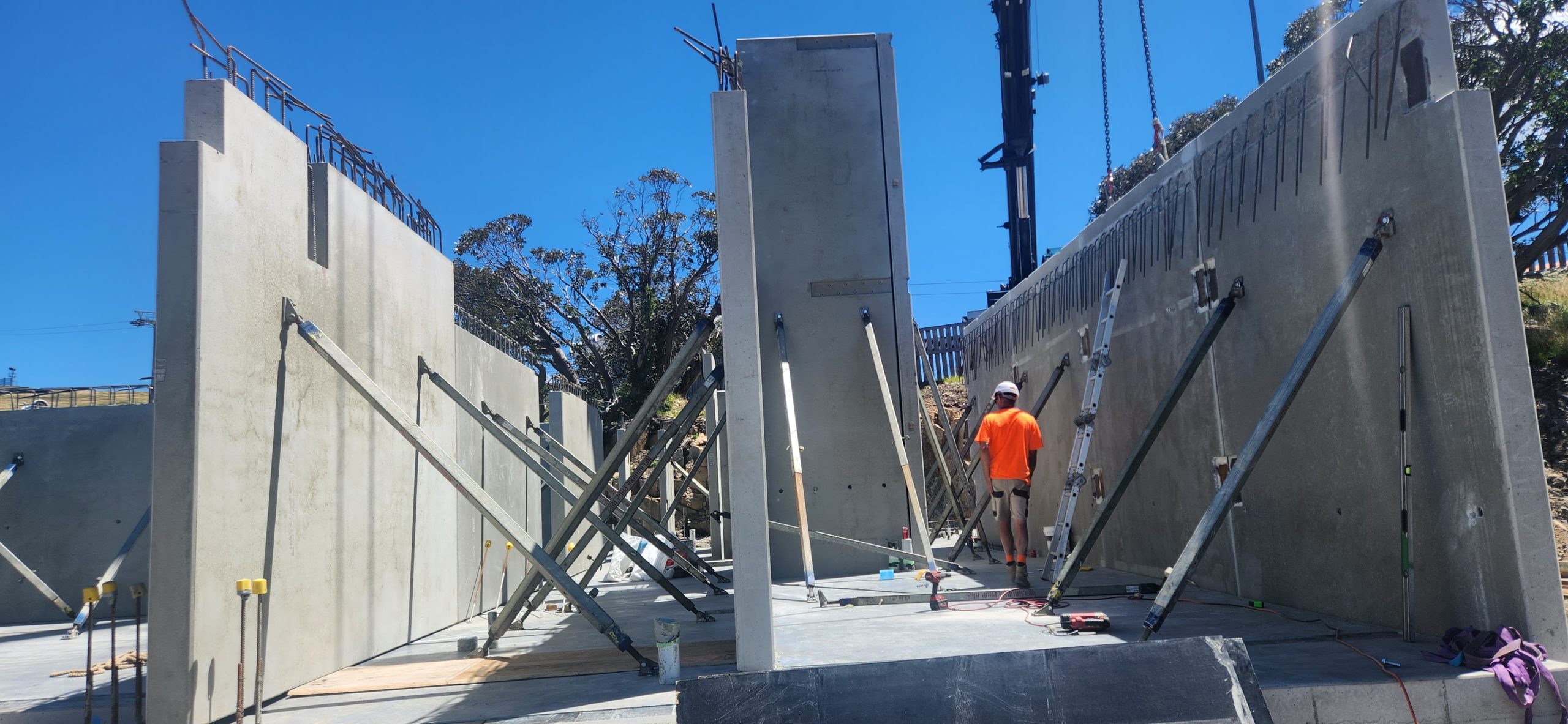
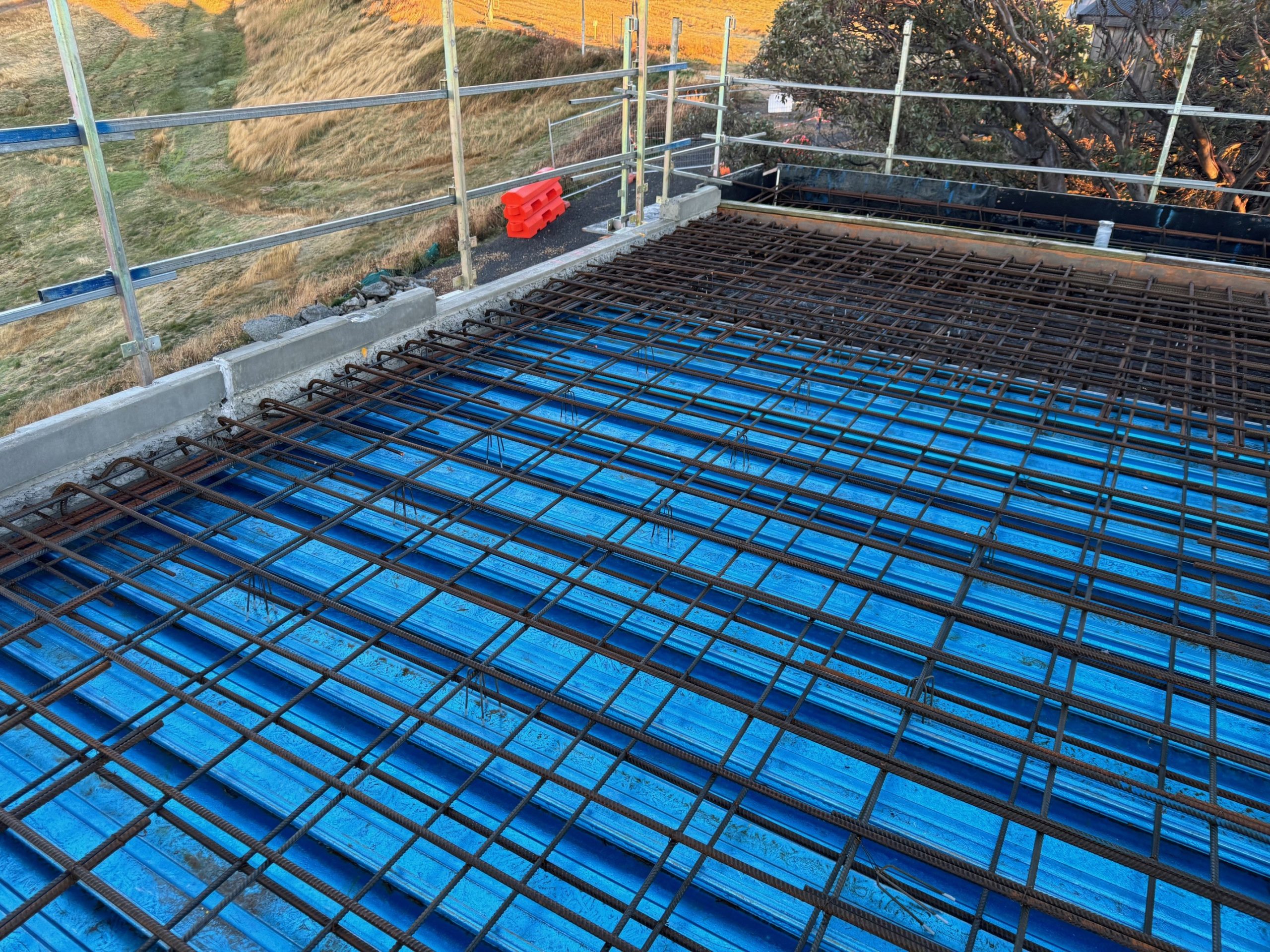
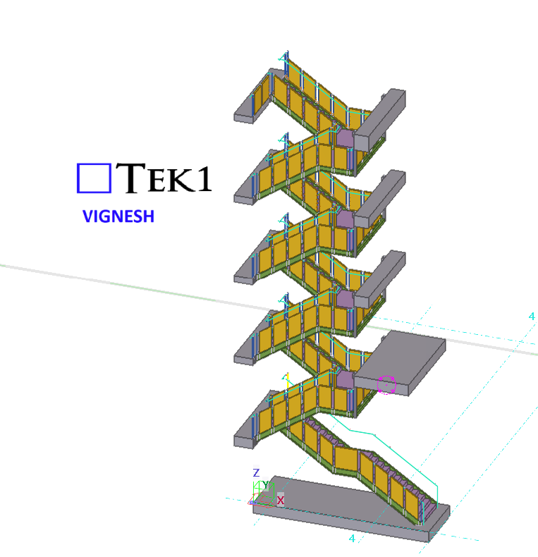
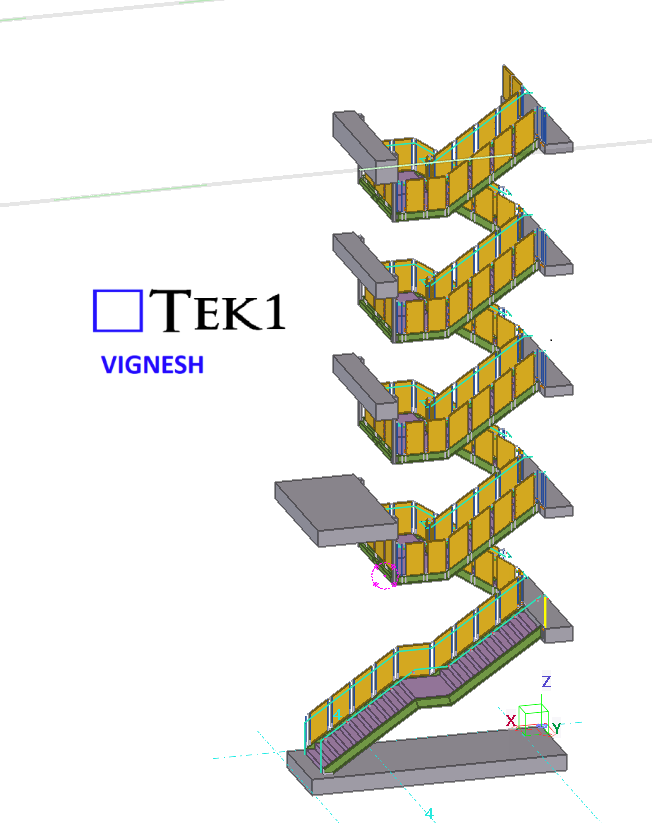
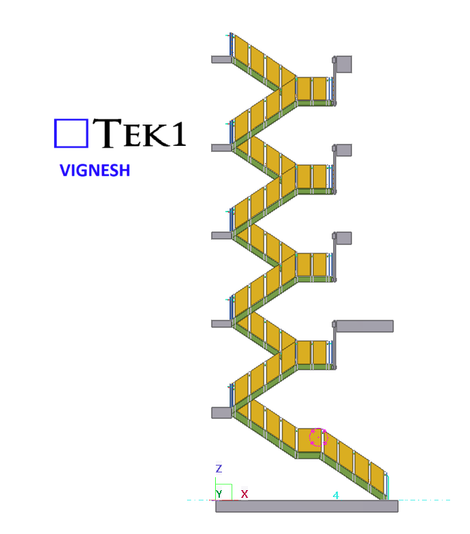
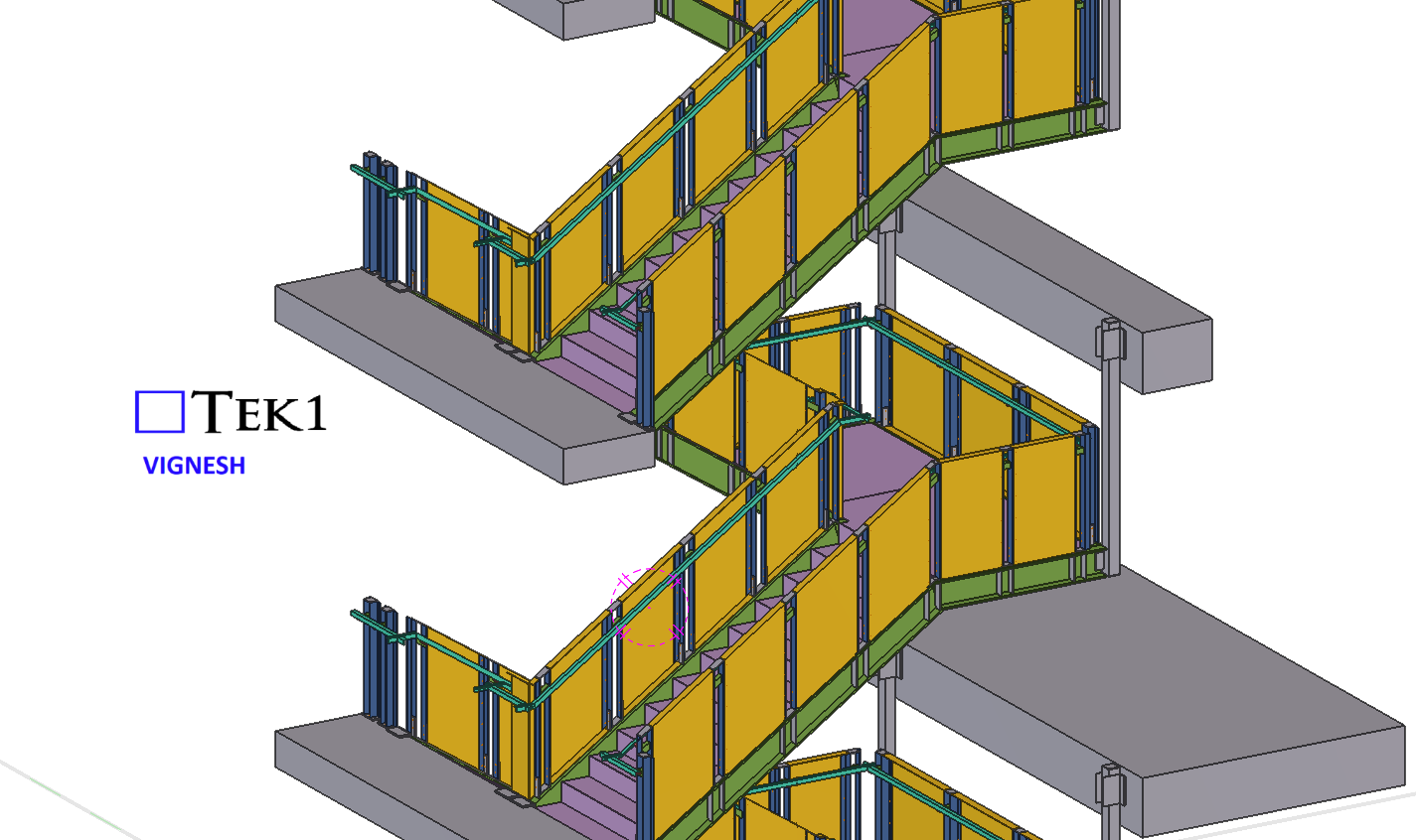
We are proud to showcase our contribution to Chalet 1 – White Horse Village, a unique and technically demanding project located in a mountainous region. This development presented several engineering and detailing challenges, and our team was honoured to be part of the solution — delivering precision, coordination, and innovation from start to finish.
Technical Challenges
This project stood out due to its unique geometry and remote location. The major challenges included:
Angled Upstand Panels: Required precise detailing to ensure proper alignment and installation
Angled CIP Connections: Demanded detailed planning and coordination for constructability
Hybrid Slab Systems: Seamless integration of different slab types needed high-level coordination between trades
Mountainous Terrain: Site conditions added complexity in anchorage planning, tolerance adjustments, and logistics
Tools & Collaboration
Software Used: Revit & AutoCAD
Team Collaboration: Close coordination with structural engineers, architects, and production teams ensured accuracy, clarity, and timely delivery of shop drawings
Are you finding precast estimation a demanding task?
Imagine offloading the time-consuming aspects of this process, freeing you to focus on more critical activities. At Tek1 Pty Ltd, we excel in providing fast and accurate takeoffs for precast projects, often at a fraction of the cost you might expect. You can rely on our expertise and extensive experience to deliver exceptional results.
Our process begins with your structural and architectural PDFs. Utilizing the panel spliting details from the structural precast elevations, we proceed with a detailed analysis.
We meticulously number all panels, assigning crucial data such as thickness, material, and panel type. This intelligent data within our takeoff model allows for comprehensive report generation later in the process.
The panel type information also captures reinforcement details, including rebar weights, perimeter bars, and any additional mesh. For panels requiring patterned or special moulds, including brick snap panels, we identify and mark them accordingly, even specifying the number of special moulds needed.
Our summary report provides a comprehensive overview, including:
Number of panels
Thickness summary
Gross and net area calculations
Concrete volume
Panel weight (concrete + reo)
Number of meshes and reo weight (excluding ligatures)
Perimeter bar weight
Caulking and grout lengths
Panel types and strengths
Concrete mix and any colored concrete specifications
Quantities of Bricsnap, Reckli, and Feature panels
Number of moulds required
Maximum panel size and its corresponding number
IFC model compatibility with Trimble or Autodesk
A QR code linking directly to the model for easy viewing
Thickness summary
Furthermore, we proactively identify any potential for optimization or issues related to buildability and transportation, providing comments along with the relevant panel mark numbers.
If you believe our services can bring significant value and allow you to concentrate on higher-priority tasks, please don’t hesitate to call or email us.
You will be surprised how economically we can do the take off for you
If You Have to share a Model With Consultants, but they do not have the Same Software.
To guarantee that your content File format is compatible with several tools.
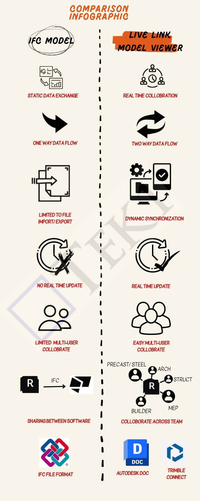
You are creating a static data exchange project, not real-time collaboration.
Use Live Link Model Viewer When:
You want real-time collaboration between two to n users or teams.
Save time and effort lost to exporting/importing files from one software tool to another
You are working on a multi-disciplinary project that needs coordination, such as Arch, Struct, and Service Engineer design.
Conclusion
If you’re looking for a simple, static way to share data between software tools, IFC is the way to go.
However, if you need real-time collaboration, dynamic data sharing, and seamless teamwork across disciplines, a Live Link Model Viewer is a better choice.
(Temporary Fixing Inserts for As-Cast Element Tolerances)
INTRODUCTION:
To ensure proper alignment and structural efficiency in the handling and installation of prefabricated concrete elements by placing temporary fixing inserts within the allowable as-cast dimensional tolerances as specified in Australian Standard AS 3850.2:2015.
Inserts for the temporary attaching of prefabricated concrete elements shall be placed within the nominal dimensional tolerances provided by the as-cast state, in order that there is proper alignment and structural efficiency for handling and installation.
INSERT LOCATION TOLERANCES FROM A SPECIFIED POSITION
TYPE OF INSERT
TOLERANCE, mm
Face lifting Bracing Strongback Edge-lifting Longitude Thickness
±20 ±50 ±5 ±5 ±20 ±5
The temporary elements are only used for demoulding, transport, erection.
Once the panel shop drawing is issued for construction (IFC), the manufacturing process begins.
However, the elements may not exactly match the shop drawing dimensions due to factors such as concrete pouring and vibration.
These factors can lead to dimensional variations. In Australia, precast concrete manufacturing follows the standard AS 3850.2:2015, which provides insert location tolerances relative to the specified position.
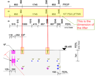
(For Example):
This is the actual dimension of the Edge lifter
This shop drawing is for IFC; after that, it will be used for the manufacturing process.
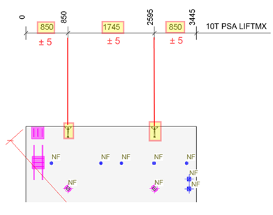
(For Example):
The edge lifter dimension after curing:
After curing, the edge lifter dimension is acceptable with a tolerance of ±5 mm, as specified in the Australian Standard AS 3850.2:2015 (refer to Table 2.7)
To explain the application and detailing requirements of temporary loose plate connections used in precast panel-to-panel joints. This document outlines the types of connections (parallel and corner), their structural purpose during erection, and their specific use in warehouse and multistorey buildings. It also highlights the importance of accurate detailing for cast-in ferrules and placement considerations to avoid clashes with structural elements like roof steel.
The plate connection used in Precast Panel to Panel connection depends on weight, wind, loading, and shape. The plate also contributes to the additional strength of the panels.
These connections are used after erection, as they are already structural connections at the panel bottom (grout tube with dowel bars), along with the brace connection. After that, an additional temporary plate is connected from panel to panel for extra strength.
THE LOOSE PLATE TYPE OF CONNECTION:
Panel to panel (Parallel).
Perpendicular panel with corner connection.
This type of connection is commonly used for panel-to-panel connections.
1.PANEL TO PANEL (PARALLEL):
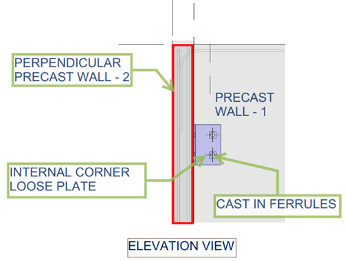
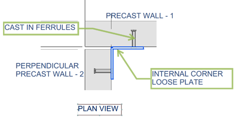
2.PERPENDICULAR PANEL TO PANEL CONNECTIONS AT CORNER JOINT
APPLICATIONS:
WAREHOUSE BUILDING CONDITION.
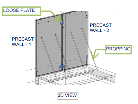
The panel-to-panel connection adds additional strength and also helps with propping.
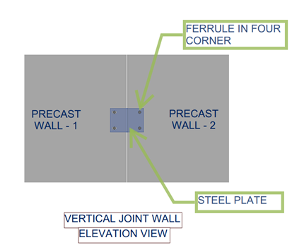
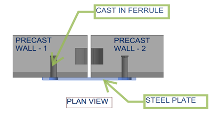
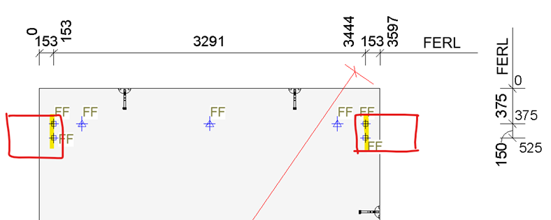
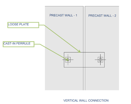
The loose plate connects to the panel surface with the help of cast-in ferrules.
This type of connection is mostly used in warehouse projects, and the plate is usually not removed after erection.
The detailer should provide exact locations with dimensions for cast-in ferrules. For example, refer to the drawing below.
This type of connection is placed inside the building to avoid affecting the exterior appearance.
MULTISTORE BUILDING.
Basically, precast panel-to-panel connections involve steel loose plate connections to support the erection process. Mostly, this type of plate connection is temporary.
Once the precast wall is erected, the loose plate is connected to the cast-in ferrules with the support of propping.
Once panel erection is completed, the loose plate will be removed. The main reason for removing the plate is to achieve the panel finish.
This type of connection is placed inside the building to avoid affecting the exterior appearance.
NOTES:
Generally, position all precast connections below the roof steel to avoid clashes with any roof steel works. When placed above the roof steel, they may interfere with the installation or alignment of roof components.
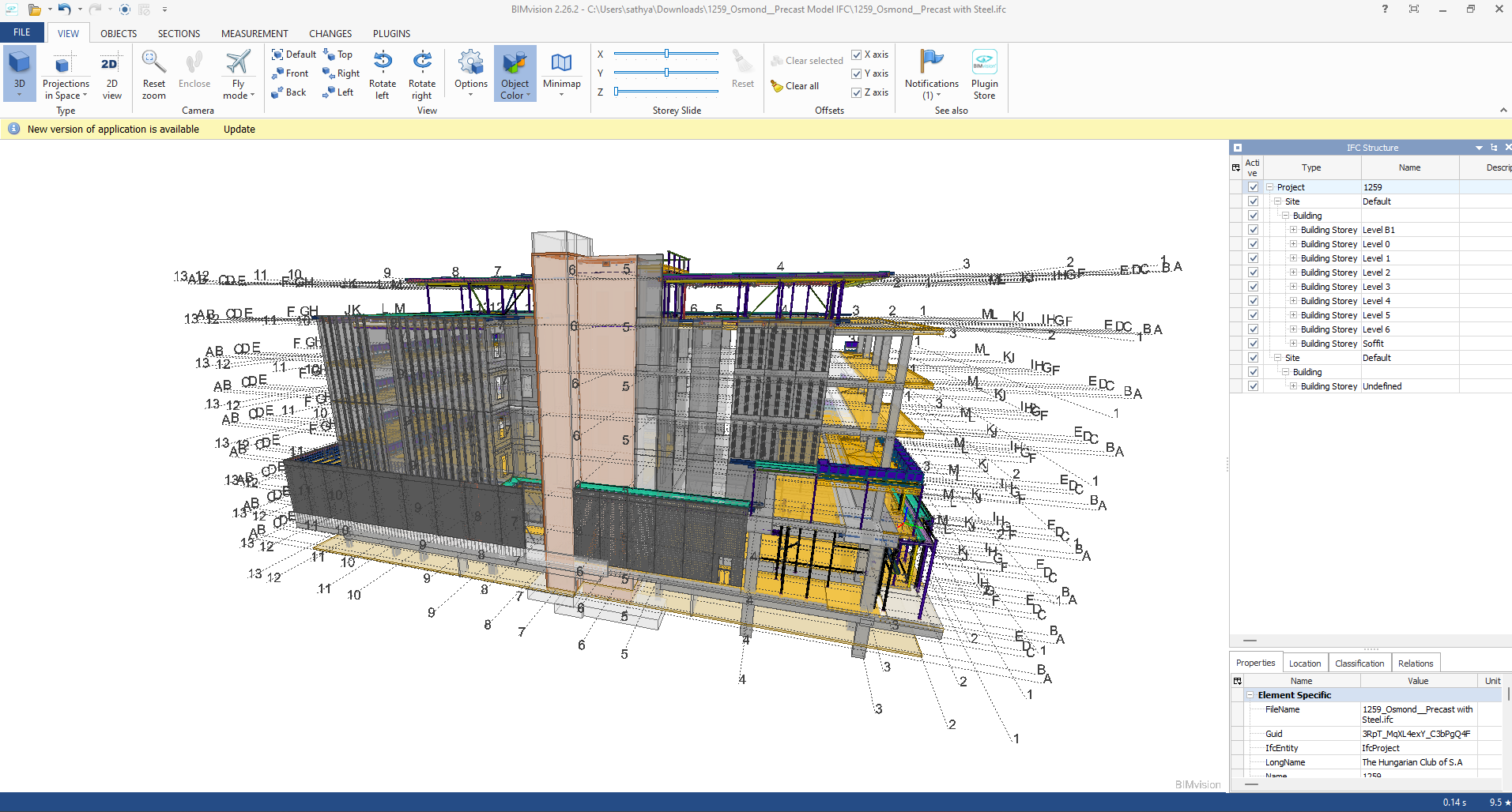
Industry Foundation Classes (IFC) is an open file format developed by Building Smart Alliance. It is an international data exchange standard for exchanging building information across different software platforms. An IFC Model is just a model of a building or a construction project with all geometric, structural, and semantic information.
Key Features of IFC Models:
Open Standard: IFC is vendor-independent, i.e., any software that supports it can be accessed, without regard for the vendor.
Static Data Exchange: It is mostly utilized for data exchange between software tools, data import, and export. For instance, an architect can create a model using Revit and export it as an IFC file, which can then be imported into structural engineering software like Tekla or SAP2000.
Limitation of Real-Time Coordination: IFC files are representations of the model at a specific moment. Changes in one application are not duplicated in another except where the file is re-exported and re-imported.
Use Cases:
Exchange of models between stakeholders with various software.
Ensuring interoperability in interdisciplinary projects (e.g., construction, engineering, and architecture).
Advantages of IFC Models:
Encourages collaboration and interoperability in BIM workflows.
Reduces errors by making sure all stakeholders are working from the same information.
Allows clash detection and coordination between different disciplines.
B. Live Link Model Viewer
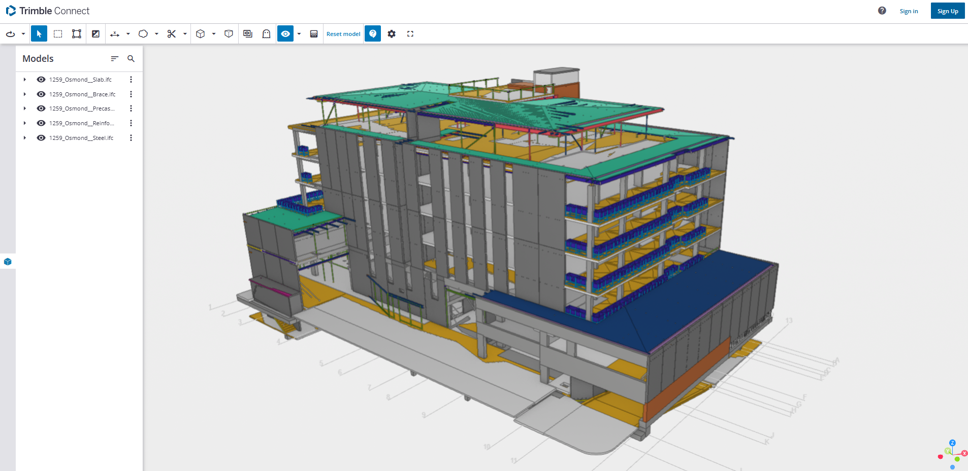
A Live Link Model Viewer is software that enables real-time sharing and visualization of BIM models on various software platforms. Unlike IFC models, which are pre-exported static files, a Live Link Model Viewer enables multiple users to work on the same model at the same time using different software programs. Common examples of Live Link Model Viewers are:
Revit Live: A cloud-based collaboration platform by Autodesk.
Trimble Connect: A BIM data management and sharing tool.
Key Features of Live Link Model Viewers:
Real-Time Collaboration: One software application’s changes are reflected immediately in the model viewer and other linked applications.
Dynamic Data Sharing: Unlike static IFC files, Live Link Model Viewers offer dynamic, real-time linking between software applications.
Multi-User Collaboration: Multiple stakeholders can view and edit one model at the same time even though they are in different software.
Use Cases:
Real-time collaboration among architects, engineers, and contractors.
Collaborative design review and clash detection.
Smooth communication between teams working on different software platforms.
Advantages of Live Link Model Viewer Benefits:
Make collaboration more effective and faster.
Eliminate the need for repeated file imports and exports.
Enhance accuracy by getting the entire team to work on the current version of the model.