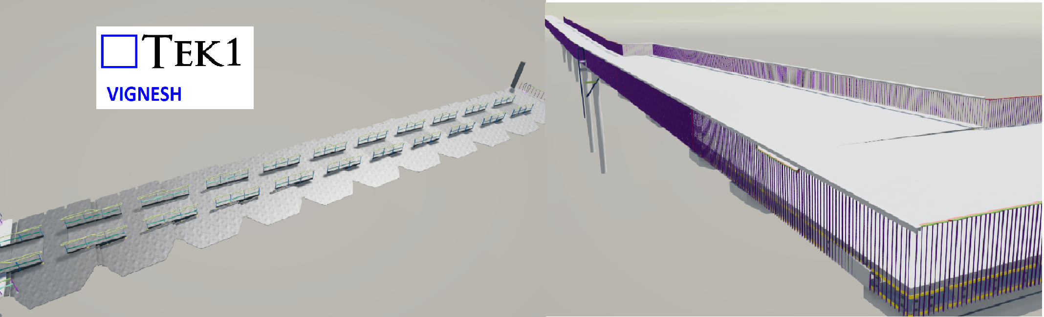
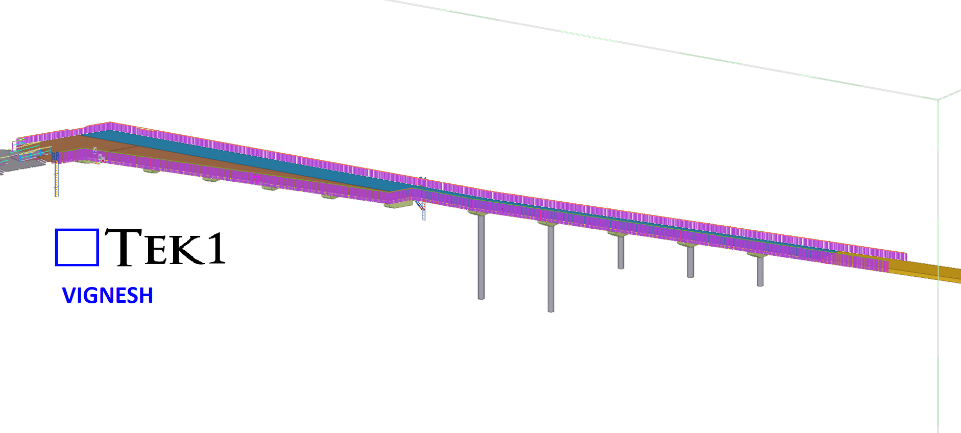
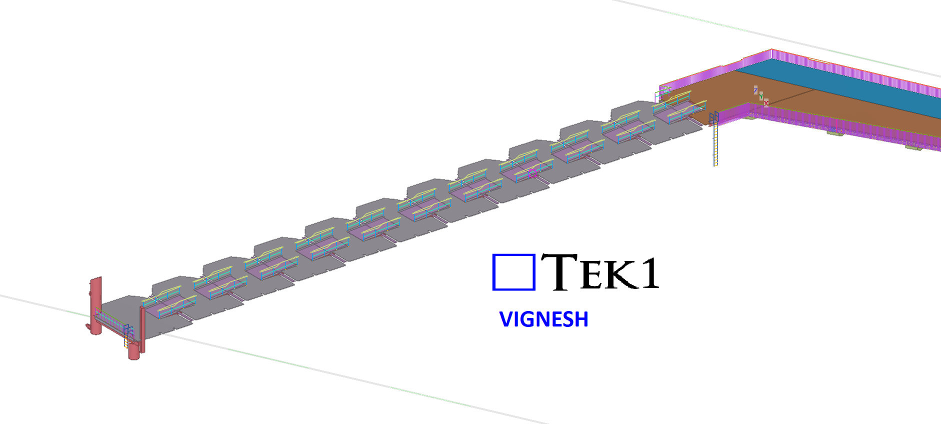
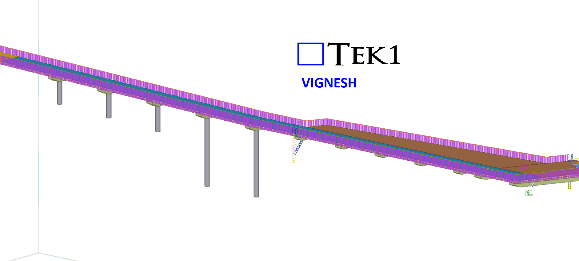
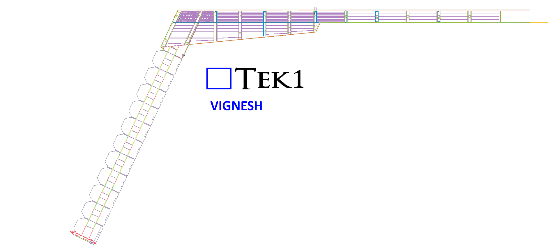
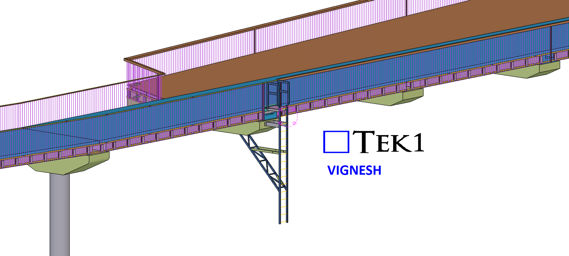
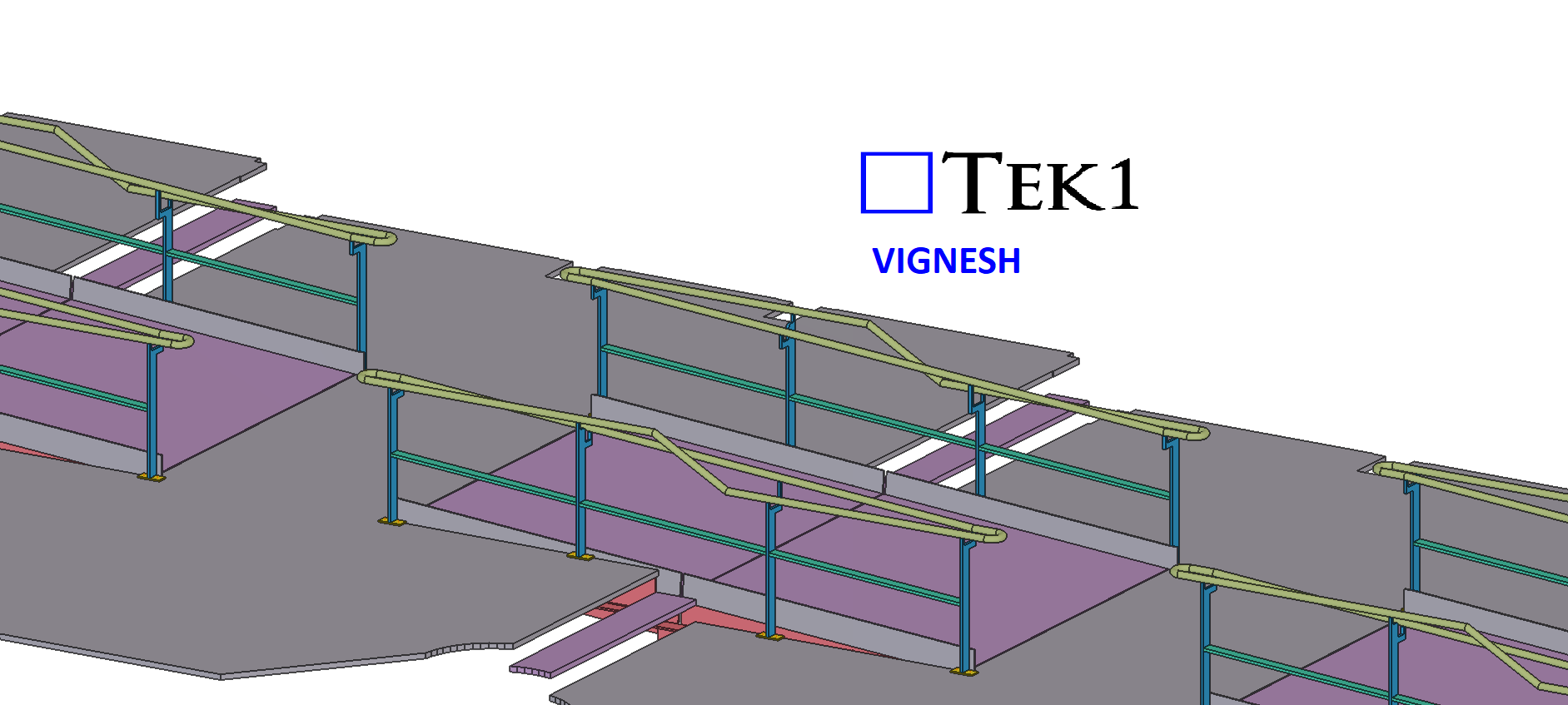
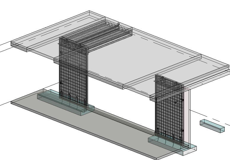
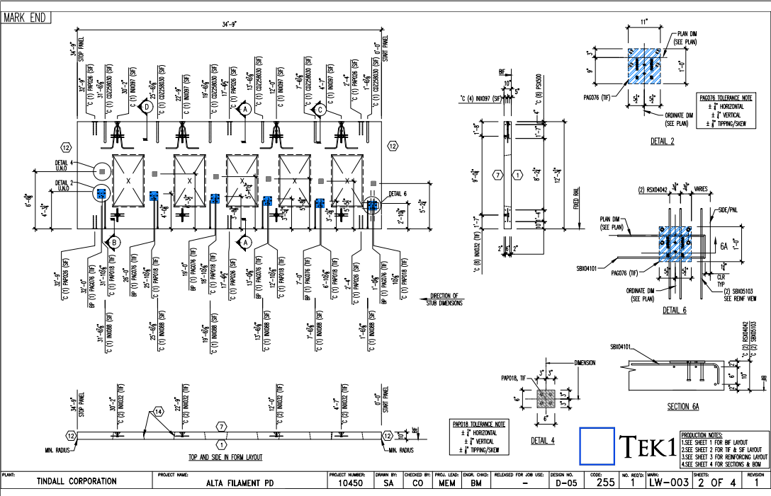
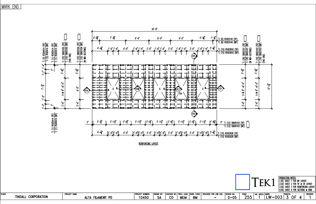
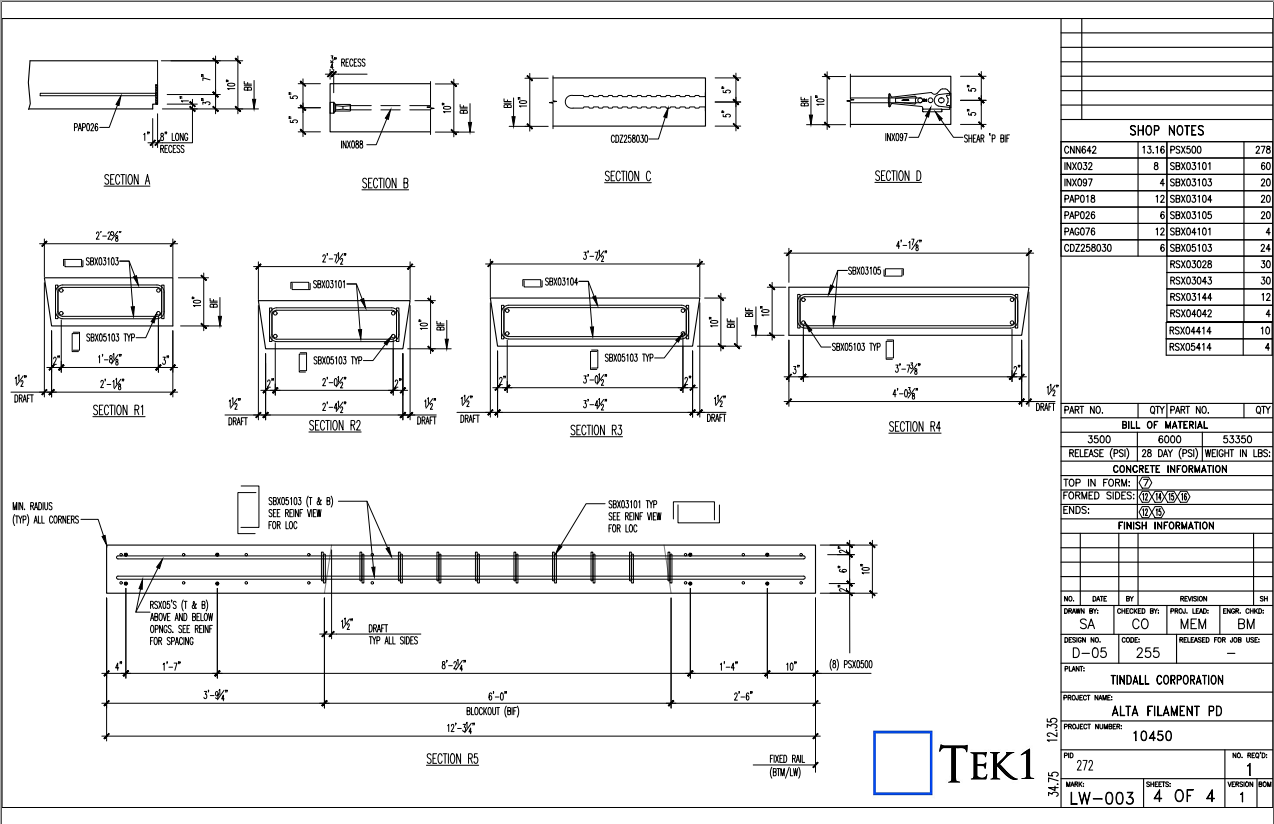
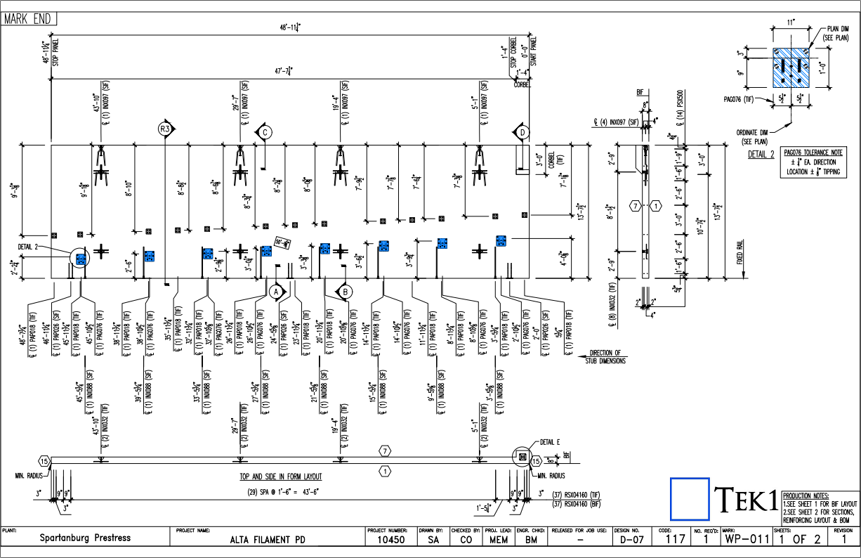
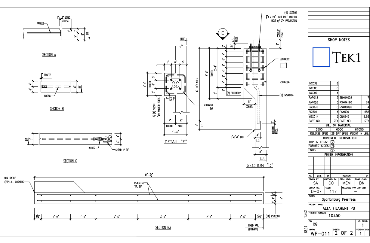
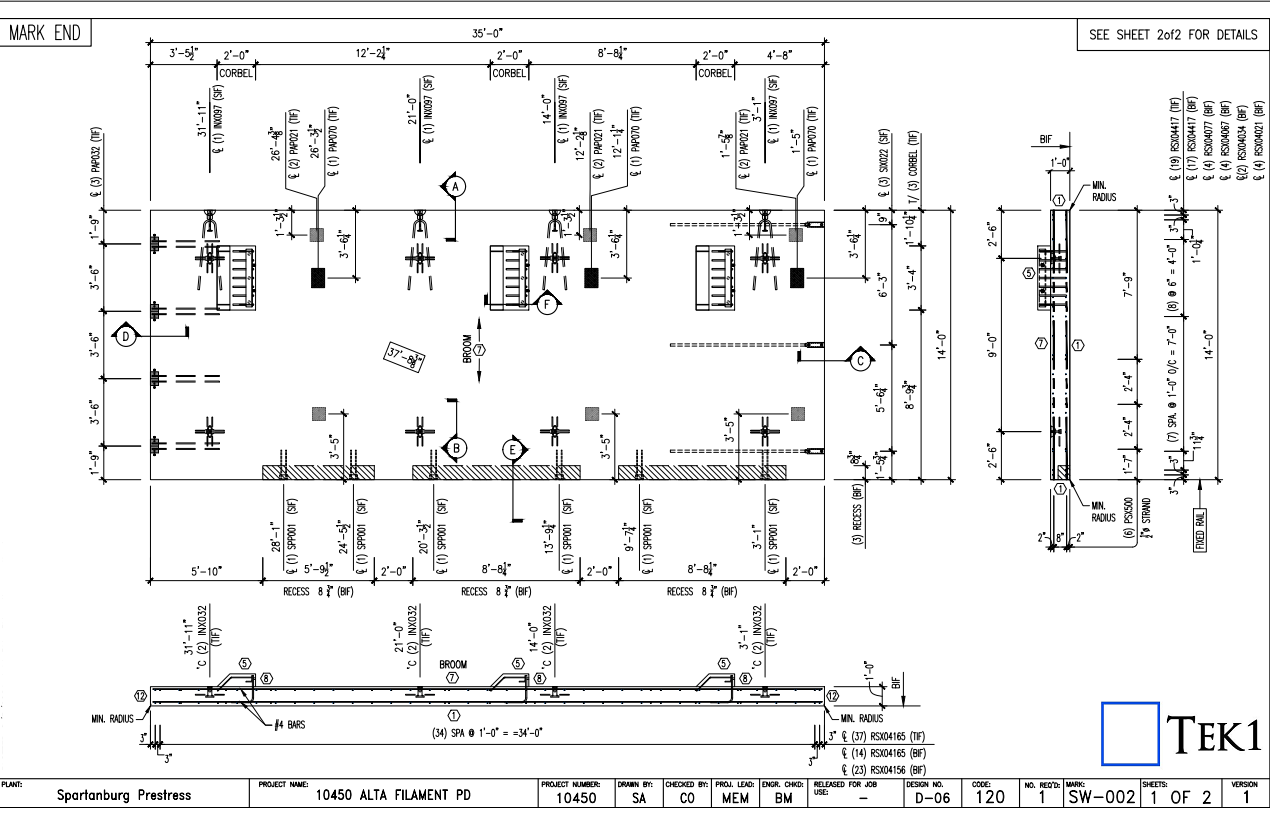
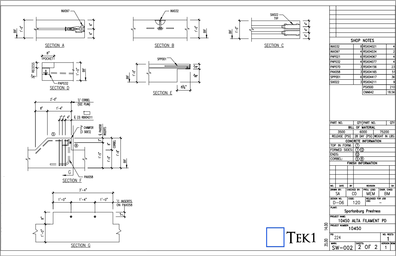
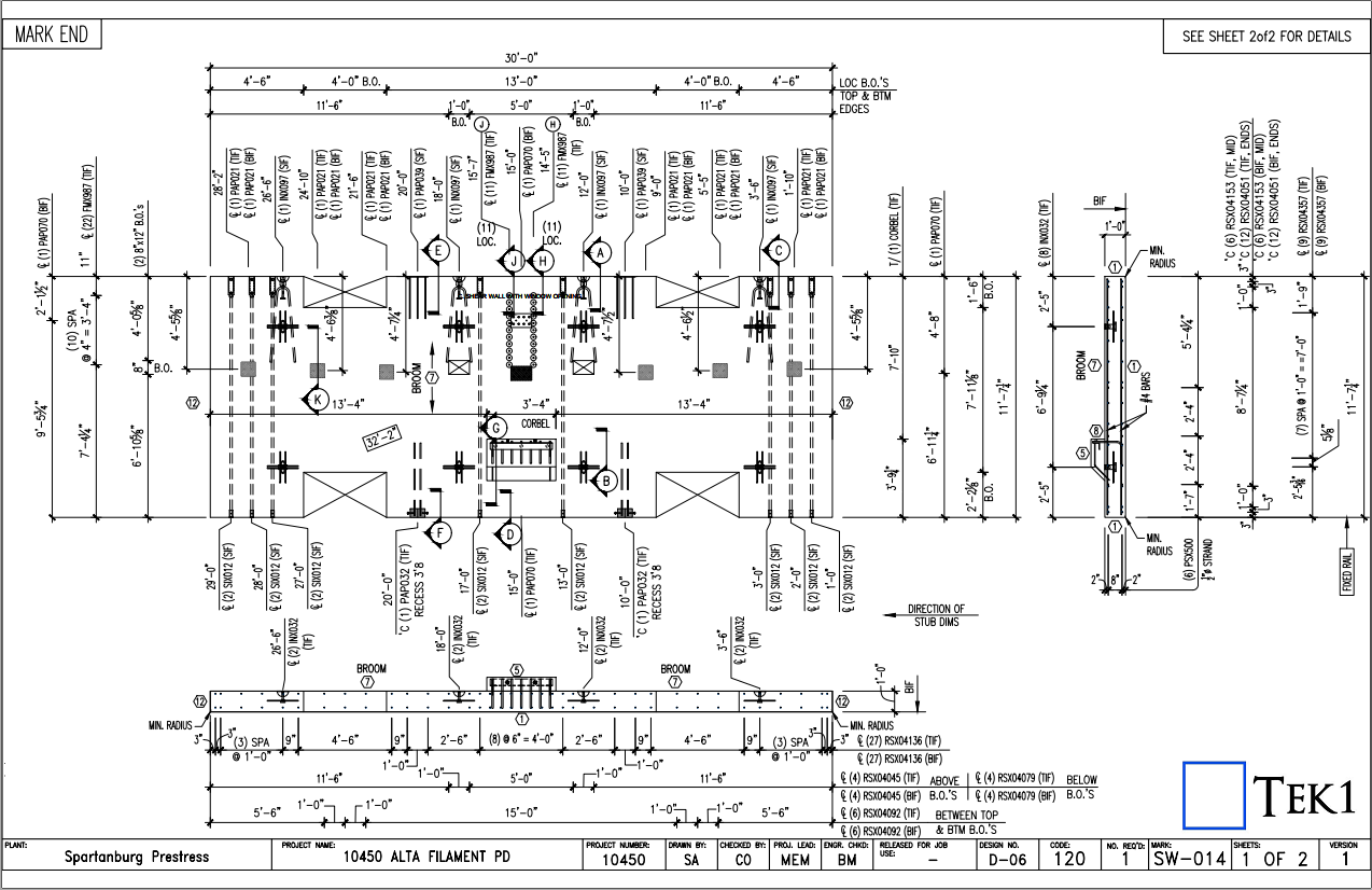
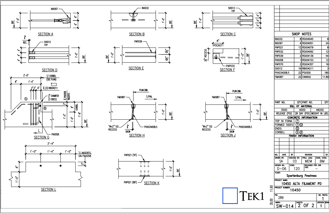
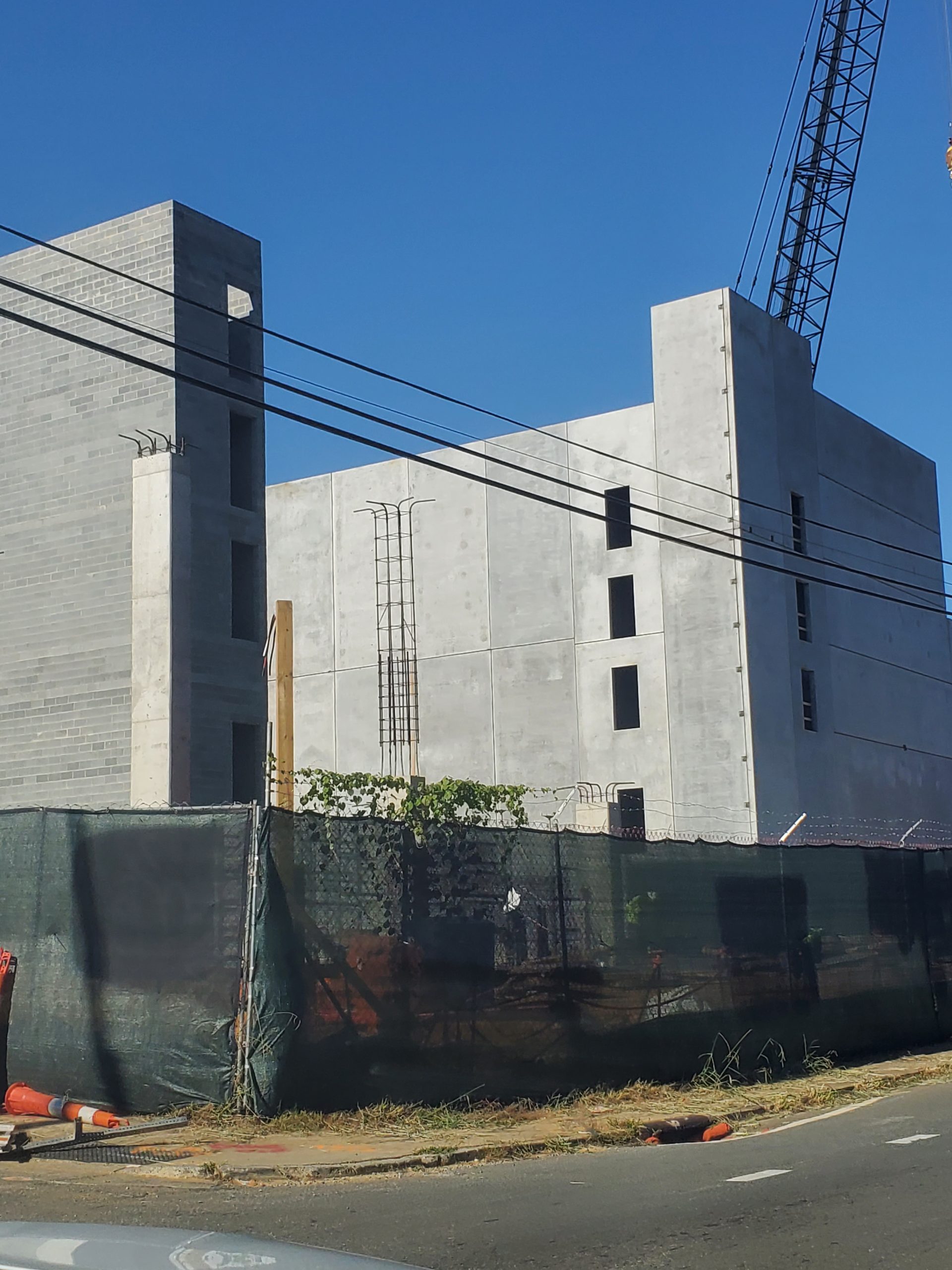
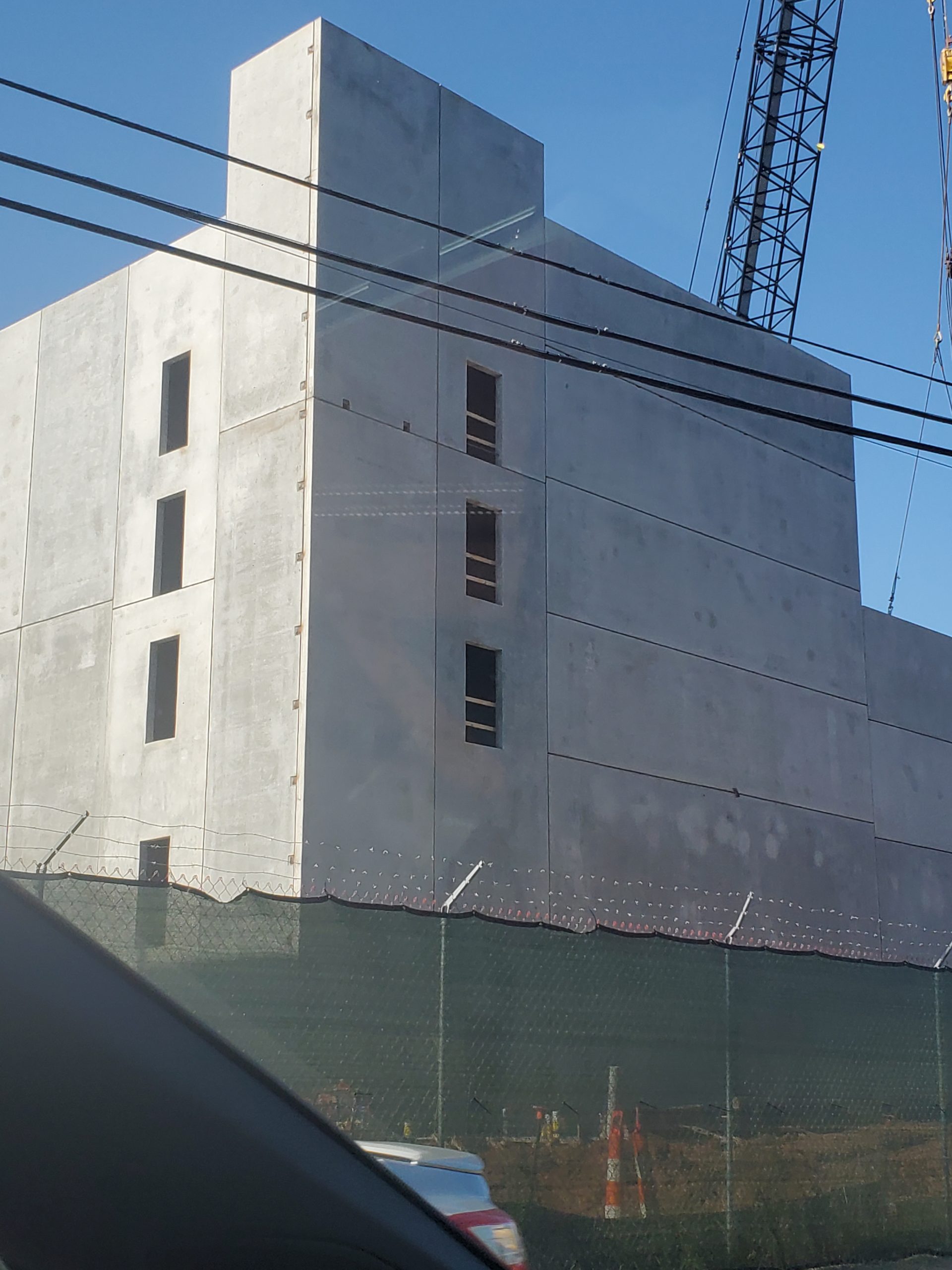
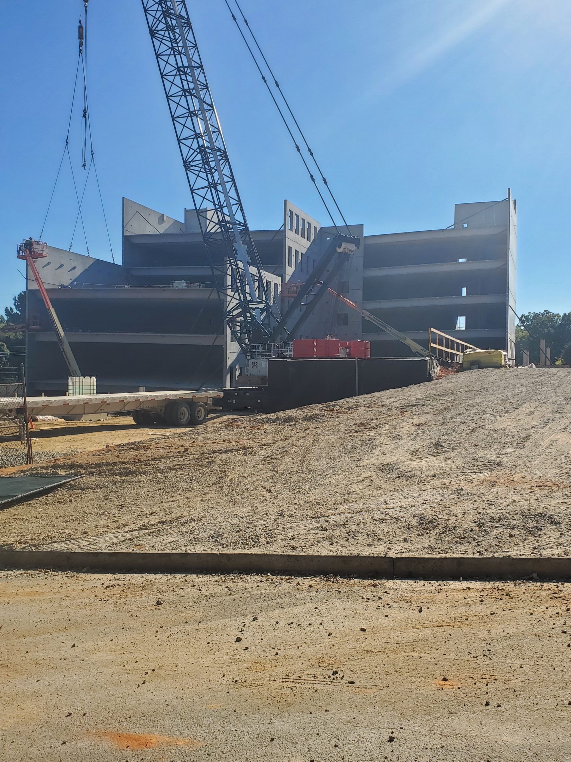
This was a complex project, but we successfully delivered it. Our scope included the balustrade around the bridge, which needed to be provided in multiple panels. By utilizing advanced modeling techniques, we were able to complete it within a significantly shorter timeline.
Since the structure is above the sea, we provided several cost-saving ideas for both erection and fabrication to optimize the process.
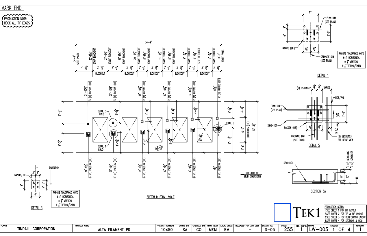
This was drawn by Tek1 (Vignesh), if you want shop drawings for a project you are working on, feel free to call Koshy on: (03) 9560 6397.
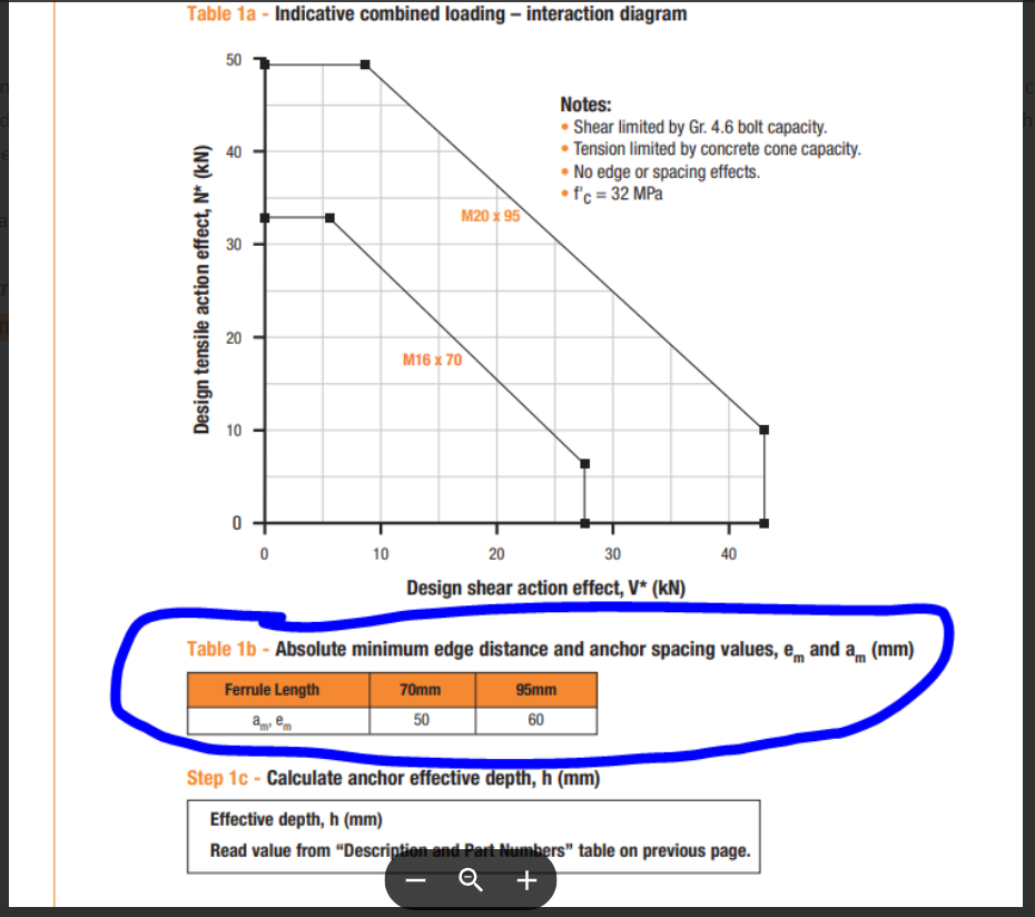
Please note that the spacing and edge distances given in the ferrule tables is for design purposes only and not a minimum for actual installation. That is the dimensions given are for each insert to achieve 100% capacity. They can be placed closer. It just means their combined capacity will be reduced. The same is for drilled and epoxied bars.
🚀 Expert Steel Detailers Align Steel and Precast 🌟
In complex construction projects, effective collaboration between steel and precast detailing teams is crucial. Proper coordination ensures smooth project workflows, minimizes delays, and reduces unnecessary costs, ultimately benefiting the client. During our recent team meeting, we explored specific challenges and solutions for optimizing the coordination process.
Here’s a comprehensive breakdown of the key strategies discussed, along with insights into how we plan to implement them for better efficiency.
1. Clear Communication on Structural Changes
Challenges: Both the steel and precast teams base their work on structural and consultant drawings, but adjustments often arise during the practical implementation. These changes can significantly impact project timelines if they aren’t communicated promptly.
Solution: Any modifications in the steel model must be shared with the precast team, allowing them to update their model and drawings accordingly. This is essential to avoid rework and maintain alignment. Our MD emphasized the importance of discussing changes before implementation and ensuring they are approved to minimize unnecessary adjustments.
2. Model & RFI Exchange Protocols
Issue: Delays can occur when teams do not exchange their models and RFI’s efficiently, leading to inconsistencies between steel and precast elements.
Solution: To streamline coordination, the precast team should provide the completed model to the steel team, and vice versa. Regular model and RFI’s exchanges help both teams stay in sync and prevent potential clashes in the final stages of detailing.
3. Setting and Meeting ETA Expectations
Importance: The steel team coordinator or the precast team should actively communicate expected completion dates. This mutual accountability is essential to ensure each team is working on schedule.
Proposed Workflow: Establishing ETA checkpoints and regular updates will keep both teams informed and accountable, promoting smoother project progression.
Consequences of Poor Coordination
When coordination is inadequate, the project risks delays and escalated costs. Here are some potential pitfalls if best practices aren’t followed:
Project Delays: Misaligned timelines between steel and precast can cause setbacks, leading to extended project durations.
Waste of Resources: Inefficient communication can lead to rework, wasting valuable time and effort.
Unplanned Variations: When models are not aligned, variations can arise, leading to costly adjustments for the client.
Our Key Directives for Improved Coordination
Highlighted the following directives to improve coordination between steel and precast:
Establish Clear Responsibilities: It’s essential to specify in the initial RFI who will handle the steel detailing and who will coordinate between the two teams. Clear assignments will create a smoother workflow and enhance accountability.
Confirm Internal or External Steel Detailing: Knowing whether steel detailing will be done in-house or by an external party ensures everyone is aligned on responsibilities, reducing potential workflow disruptions.
Reduce Rework Through Precise Coordination: By following these practices, we can eliminate rework and improve project efficiency.
Future Blog Insights: Benefits of In-House Steel and Precast Detailing
Finally concluding thoughts highlighted the advantages of having both steel and precast detailing by Inhouse. Should the precast team win the job, they can propose in-house steel detailing as well. This approach offers several benefits, which we’ll explore in-depth in our next blog. Stay tuned for more insights on how integrated in-house detailing can drive smoother workflows, lower costs, and ultimately enhance project success.
Final Thoughts
Effective coordination between steel and precast teams is foundational to project success. With clear communication protocols, responsibility assignments, and regular model exchanges, we can set a new standard for collaborative project workflows. By continuing to improve these processes, we aim to offer clients timely, cost-effective, and high-quality detailing solutions.
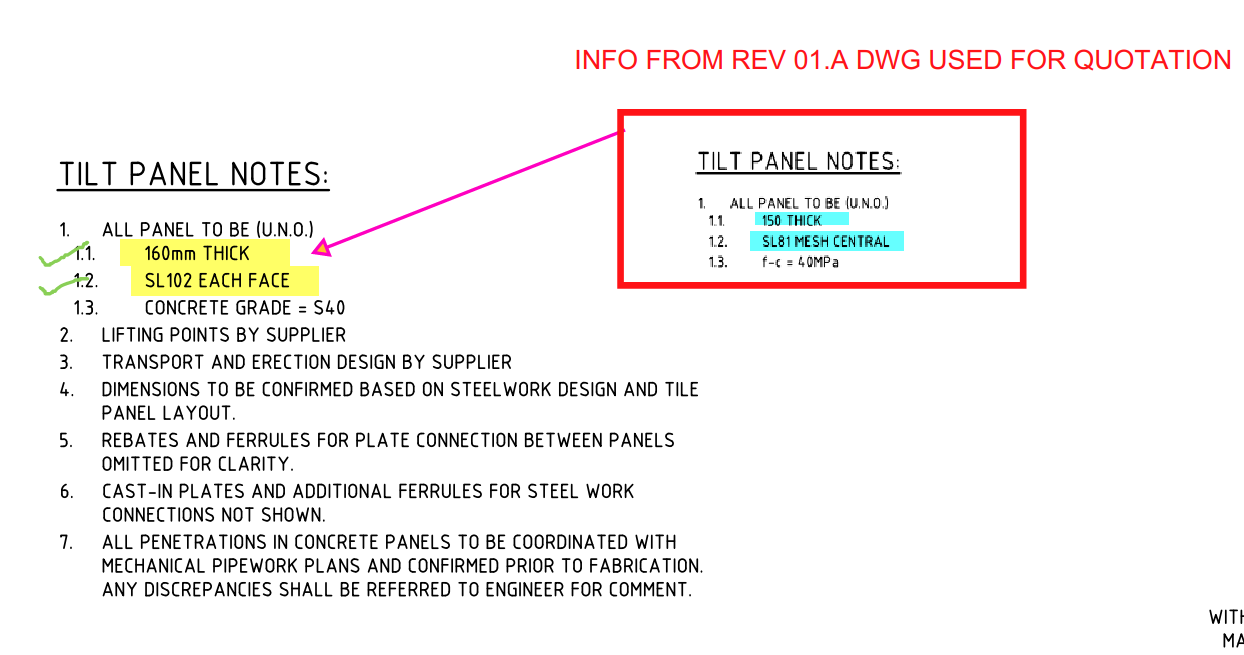
It is essential to cross-check the revised consultant drawings we receive against the original drawings from the Quotation stage before commencing the project because this may affect prices.
For example, the panel break up, or the panel specs might have changed. If they have changed, this might have a material impact on price such as concrete and reinforcement cost.
What should we do when they make changes?
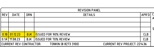
Check the consultant drawing revisions and their date (between the quotation and the current stage).
For example:
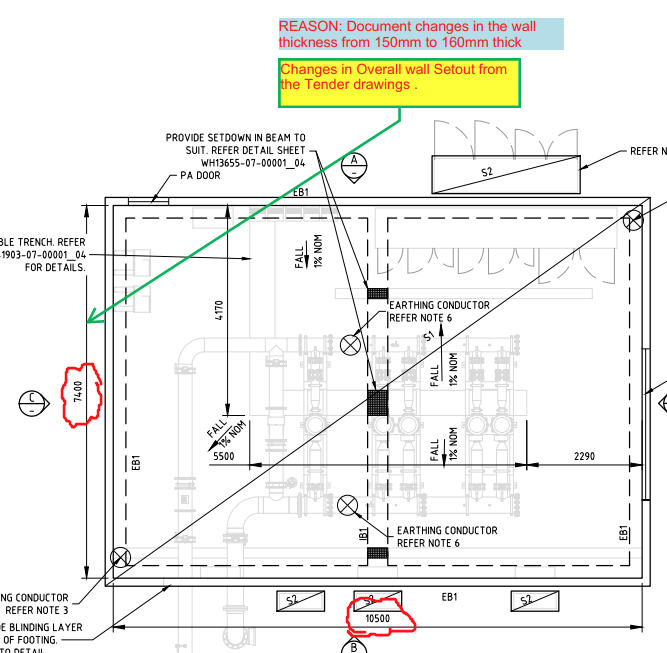
2. Highlight the changes that occurred and mark them down in the latest structural PDF.
For Example:
3. Prepare a summary document report outlining the modifications.
For Example:
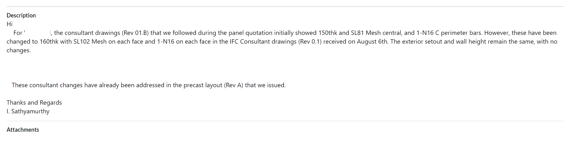
4. Inform the precast manufacturer and builder about these changes by sending the relevant information via email.
For Example:
Why do we need to check the consultant drawings?
This verification process will enable the precast manufacturer and builder to re-evaluate the timeline based on the information that was previously quoted. This allows potential Cost issues that could cause confusion or delays in the project timeline to be identified and resolved early on such as
Cost estimation of individual precast panels, including their respective panel areas and concrete volumes, for manufacture.
Cost estimation of approximate reinforcement and mesh weight requirements.
List of cast-in items and loose items required, approximate quantities.
What are the key factors that need to be verified in the consultant drawings from a precast perspective?
Panel Thickness and Types: Verify the panel thickness and types used, as specified in the Structural Drawings.
2. Panel Count: Confirm the panel count based on the panel split, as detailed in the Structural Drawings.
3. Panel Transportability and Tonnage: Conduct a transportability check and verify the tonnage of the panels from our end.
4. Panel Reinforcement:
Perimeter bar diameter
Mesh type used and its placement
Additional reinforcement provided in the panel typical detail
Reinforcement on central or either side ( specify location) (Refer to Structural Drawings for details)
5. Precast Wall Pattern and Special Moulds: Verify the precast wall pattern and special moulds required, as specified in the Architectural Drawings.
6. Panel Finish: Confirm the panel finish, as specified in the Architectural Drawings.
7. Panel Connection Details: Verify the panel connection details, if applicable, as specified in the Structural Drawings
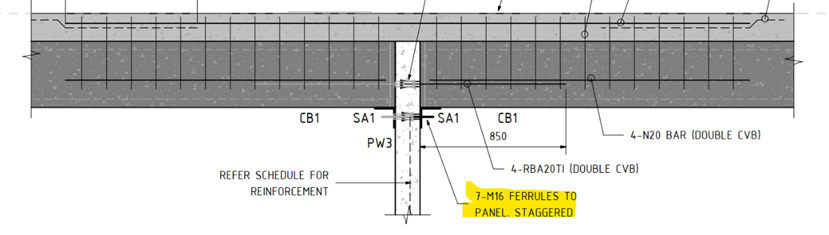
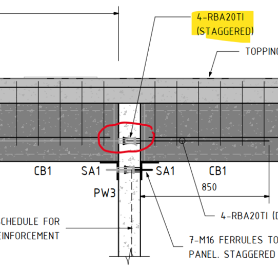
The design drawings for one of our Precast Project we were working on suggests ferrules must be placed staggered as noted below.
The Problem:
However, these casting components, such as ferrules cannot be placed on both sides of a precast panel with a thickness of less than 250mm. This mainly causes ferrules to clash along its length. This approach will not work. Can you see why
The Solution:
One of the projects, for our client involves utilizing the staggered arrangement approach. Look at the (fg.1)
(fg.1)
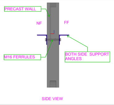
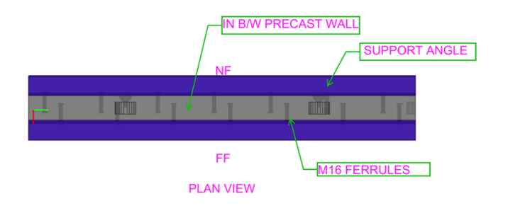
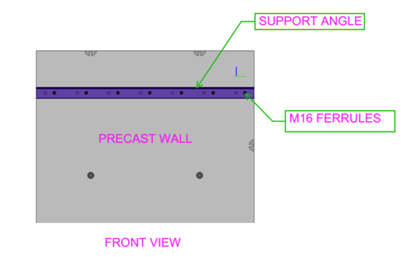
The both sides of wall are provided with support angles SA1 to hold the slab/ Beam.
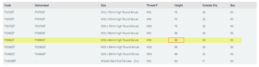
Both sides are utilizing M16 ferrules, within the panel. The issue lies in the fact that the ferrule Height measures 96mm whereas the wall thickness is 150mm.
Client using PSA Standard ferrules
Example:
Wall thick – 150mm
M16 Ferrule length – 96mm add both sides of wall
96 + 96 = 192mm (greater than the wall thickness 150mm)
The length of the PSA P1696ZF is 96mm, as per the PSA schedule.
Ferrules cannot be placed inline; the only option is to staggered them.
Look at the (fg.2)
(fg.2)
The above ferrule placement factors and consideration is not required if the panel thickness is 250mm and above.
In one of our Projects, Audi Centre Myaree for the Client PARKD Ltd, the typical structural drawing detail represents the precast wall panel which connects to the Delta core slab with RBA20TI inserts.
Two variations of Precast panel thickness have been used in this project: 150thk, and 200thk.
What is the Problem?
The Insert component RBA20TI or PTI20 are difficult to place on the precast panel face with a wall thickness of 150mm.
Cause for the Problem: Lack of minimum concrete cover is due to component length close to the Panel thickness.
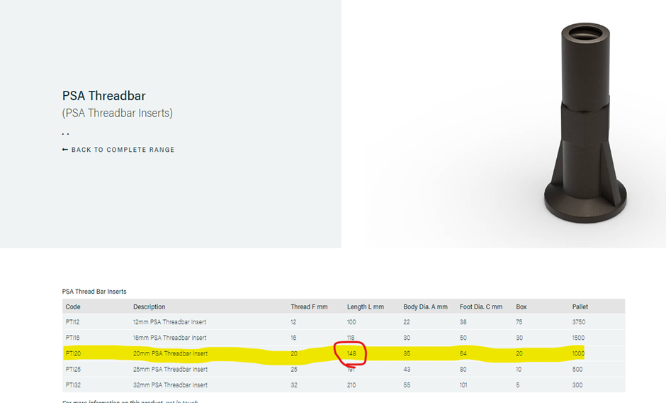
The length of PSA Thread bar Inserts PTI20 is 148mm as per the PSA Schedule.
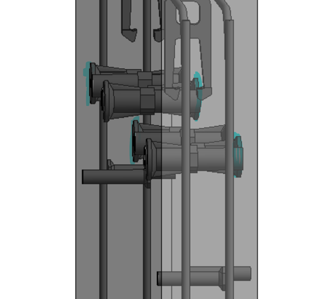
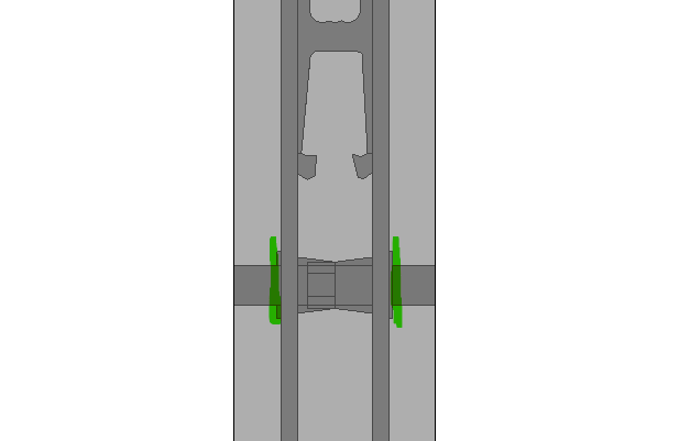
The minimum concrete cover required for this project is 30mm. However, placing the component with a height of 148mm on a Panel with a thickness of 150mm results in no space for concrete cover, as shown below in Image 1
Image 1: Plan View of 150thk Precast Panel with PTI20 Inserts on the panel face.
Image 2: 3D view of a 150thk precast panel with PTI20 Insert. The highlighted portion in blue indicates a lack of concrete cover.
3D Model Viewer Link for 150thk Precast Panel with PTI20 Insert:
To retain the 30mm concrete cover in the Precast panel, the PTI20 insert component needs to be replaced with PTI16, which has a length of 118mm. This will result in a 32mm concrete cover, satisfying the minimum cover criteria.
Image 3: Plan View of 150thk Precast Panel with PTI16 Inserts on the panel face.
Image 4: Elevation View of 150 thk panel with PTI16 Insert.
Critical Condition To be Remeber:
Although changing the insert size from PTI120 to PTI16. It is highly required to consider the structural strength of the connection.
The structural strength of PTI16 with starter bars of 16 Ø is lower than that of PTI20 with starter bars of 20 Ø.
To overcome this, it is advisable to increase the count of PTI16 insets by reducing their spacing compared to the spacing provided for the PTI20 insert.
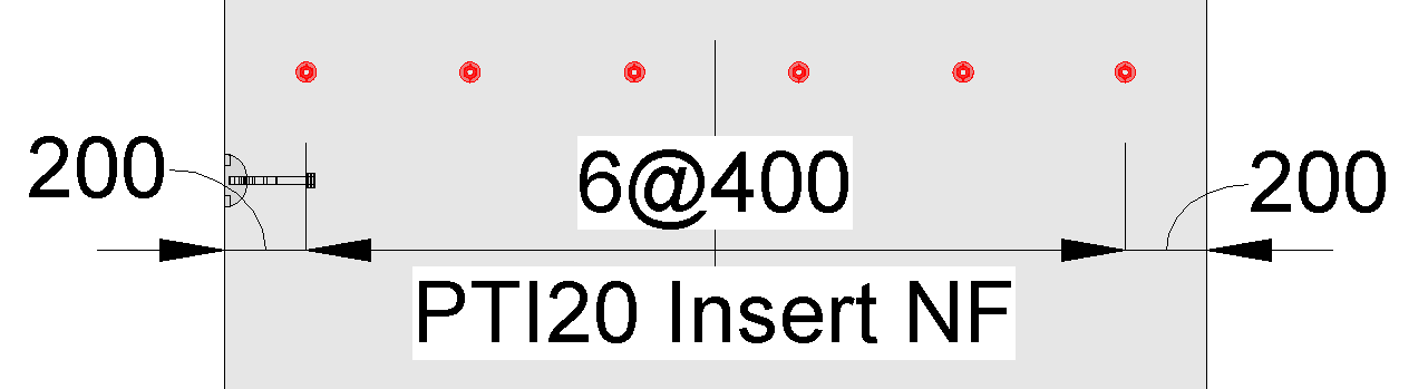
Image 5: PTI20 insert with a spacing of 400 centers
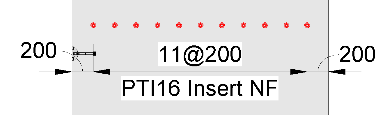
Image 6: PTI16 insert with a spacing of 200 centers (The ferrule count increased to tally the structural strength)
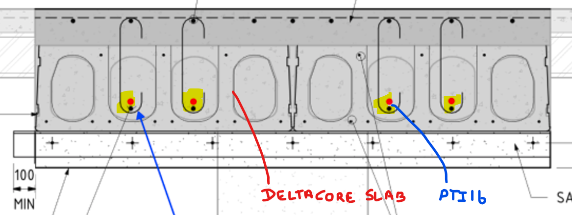
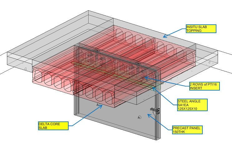
But in our case, since we are using inserts over the Delta Core slab, two rows of PTI16 inserts with a spacing of 150mm are to be placed vertically on the Precast Panel, as shown below
Image 7: Detla Cover connects with the 16Ø Starter bars
Image 8: 3D View of Precast Panel with delta Core
3D Model Viewer Link for Precast Panel with Delta core Connection:
Length of Castin components such as Inserts and Ferrule, needs to be considered about the concrete cover and Panel thickness
If the type of insert or ferrule changes, say from PTI20 to PTI16, to reduce its height, it is mandatory to increase the component count to maintain the structural strength.
Thanks to Robin Hur, Structural Engineer and Project Coordinator from PARKD Ltd, for the support and critical suggestions.