Category: Precast Blogs

Tek1 has detailed over 100,000 precast panels over 19 years.
over 90,000 were detailed under a proxy name Advanced Pretty Pictures Pty Ltd

PRECAST PANEL DETIAILING
EXPERT PRECAST PANEL DETIAILING
  • GROUT TUBE WITH DETAILS

    GROUT TUBES:

    • Grout Tubes are hollow components and are made of plastic or thin sheet metals.
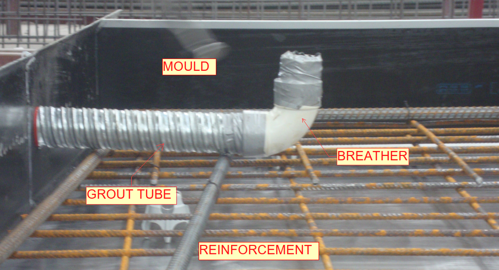
      (Refer Fig.01)
    • Grout tubes are cast into precast elements which create a void to locate and connect the elements (between two precast elements or in-situ to precast elements) together using starter bars or dowel bars.
    • Once the elements are in position, the grout tubes are filled with grouting material and locking the elements in position.

    Fig.01 (Sample bottom Grout tube with breather)
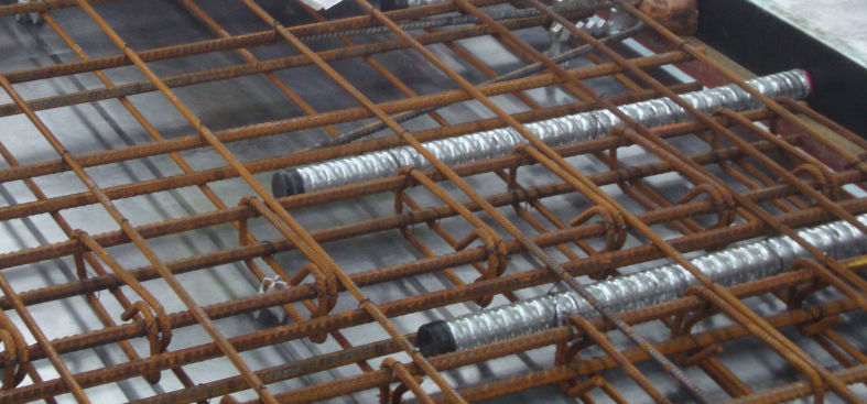
    Purpose of Grout tubes:

    • Grout tubes are used in the construction of precast concrete buildings for connecting elements like walls, tilt-up panels, beams, columns, etc.
    • It will help to increase the strength and durability of the precast or in-situ elements.

    General details for Grout tubes

    1. Hollow components with spiral designs or key ways in its walls
    2. Selection of grout tubes based on dowel size
    3. Alternatively, NMB splice sleeves or penetrations can be used or dowel bars can be directly casted if having rebar’s arrangement congestion
    4. Grouting materials must be filled for Load bearing areas and voids will be present for NLB (Non load bearing) portions.
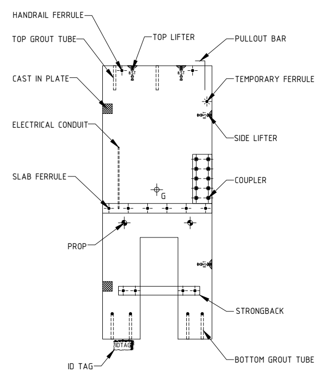
    5. Must not clash with other components in precast (Cast in plate, Lifter, Lig-cage, lig-cage hooks, Prop, Grooves, Ferrules and etc.) – Refer Fig.02
    6. Face of breather must be inside of building and must have access, must not be placed where sequential grooves or architect patterns present.
    7. If breather has no access must provide breather extent to where the access is possible (not required when it is NLB)
    8. Must have a minimum gap of 200mm with other components especially lifters & block-outs (this value can be modified, if having difficulties to maintain that gap)
    9. Avoid the Grout tube placement near to window & major openings (wherever possible)
    10. Grout tube must be placed within 300mm from panel edge. (But can be modified if having any difficulties.)

    Fig.02 (Sample Top Grout tubes)

    Advantages:

    • Lightweight and easy to process
    • Available in a range of sizes
    • It will help to reduce the construction time on site
    • Easy to connect with precast or in-situ elements

    Disadvantages:

    • The huge amount of grout tubes needed to fill up the duct in order to secure the connection between the precast wall or in-situ.
  • DOWEL BAR WITH DETAILS

    Dowel bars:

    • Dowels are short straight steel bars and also cogged bars, used to provide mechanical or structural connection between two precast elements or in-situ to precast elements.
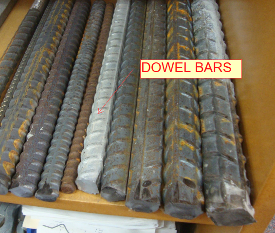
      (Refer Fig.01)

    (Fig.01) Dowel bars

    Purpose of Dowel bars:

    • Dowel bars used to maintain the horizontal and vertical alignments of slab and precast panel. (Ref Fig.02)
    • Dowel bar connection used to transfer the loads between two concrete elements or two precast elements or precast to in-situ elements. (Refer Fig.03&04)
    • Dowel bar is used to extend the structure easily with small drilling to insert the steel for the extension of the structure.

    General details for Dowels:

    • Dowel bar is a steel rods with spiral outer design. (Refer Fig.01)
    • Used in all the locations where Grout tubes are required.
    • Selection of Dowel based on Engineer requirement.
    • Dowel can either be black finish or galvanized finish.
    • Black finish for load bearing dowels and galvanized finish for NLB (non-load bearing) dowel. (It may be varied).
    • Alternatively, bars connected into NMB splice sleeves can be used. Also, starter bars can be casted into panel.
    • Plastic tube will be placed over upper half of dowel. And 20mm compressible cap will be placed over the top of the dowel bar for NLB (non-load bearing) portions whereas grouting material will cover the entire dowels for LB (Load bearing) conditions.
    • Dowels must be positioned within Grout Tubes with minimum amount of clearance on precast walls or slabs.

    Advantages:

    • It is reducing the corner cracking.
    • It will reduce joint faulting.
    • Dowel bar is also used to reduce the deflection and stress.

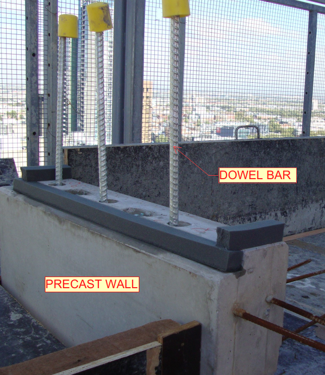
    (Fig.02) Precast wall connection

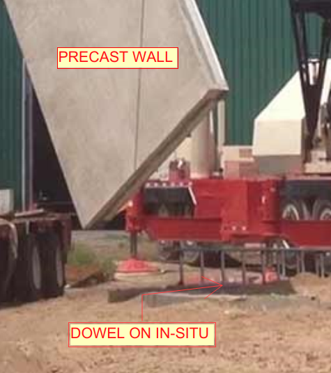
    (Fig.03) – Precast to in-situ connection
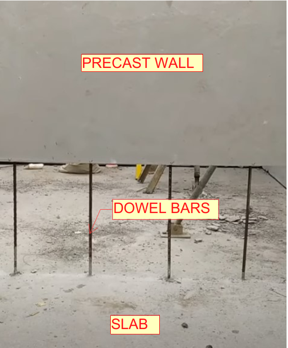
    (Fig.04) – Precast to slab connection
  • STRUCTURAL CORE PLAN AND ELEVATION DRAWINGS STUDY

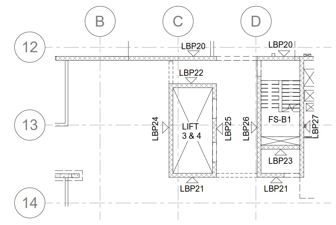
    1. Core plan shows the core wall, shear wall and overall slab boundary. (Only if it is provided by separate structural engineer specifically working for cores & shear walls).
    2. Also, it’s shown the elevation number and viewing direction. (Only if it is provided by separate structural engineer specifically working for cores & shear walls) – Refer Fig 01.
    3. Precast legends will be provided at title sheet.
    4. If too many building means, they highlighted the site key plan with current building.
    5. For single building area of working, they provided the key plan with elevation numbers and views. (Only if it is provided by separate structural engineer specifically working for cores & shear walls).
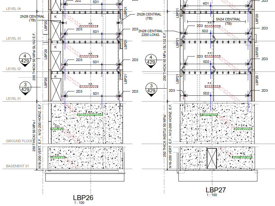
    6. In Core/Shear walls elevation, concerned engineer will provide below details – Refer Fig 02
      • Dowel bar requirement
      • Tension bar requirement
      • Thickness of panel
      • Grade of panel
      • Reinforcement requirement (in some cases it will be given in a separate sheet)
      • CIP requirement
      • Wet-joint details (usually wet joint only specified. Brief details will be given in separate sheet)
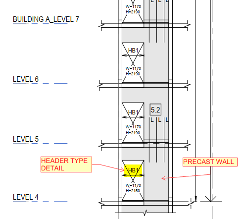
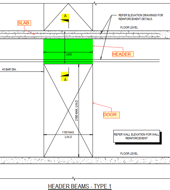
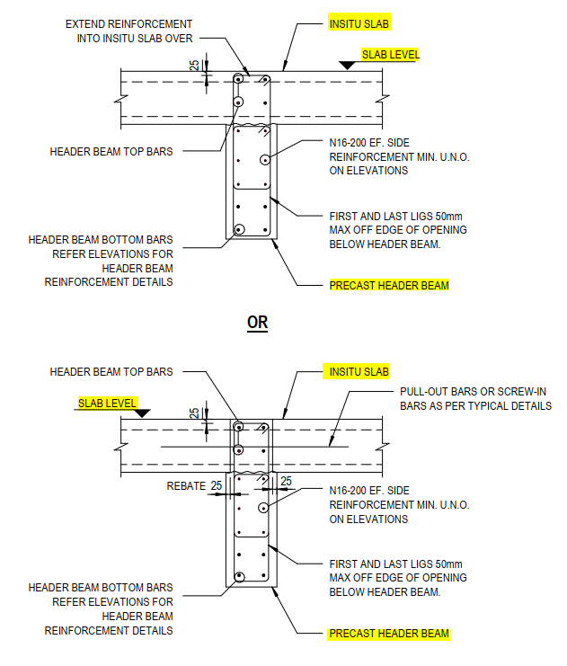
      • Header detail schedule type (in some cases header type only given, and will be defined in another sheet)
    7. In core elevation and plan, we prefer to give more importance to elevation than plan, if any issue in it we can raise RFI (Before raising RFI we have to completely analyses the discrepancy, and make a call inward and finalize the deviation. If it is not finalized then only, we can raise RFI (Request for information).

    (Fig.01) SAMPLE CORE KEY PLAN

    (Fig.02) SAMPLE CORE ELEVATION

  • ARCH STAIR PLAN DETAILS AND DRAWING STUDY

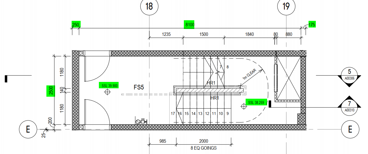
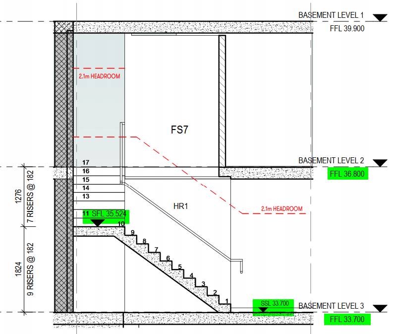
    1. Stair or fire stair drawings are used to find the stair landing RL, landing slab set-out (X-axis distance), fire penetrations and stair pressurization riser details.
      (Refer Fig .01 & 02)
    2. This drawing package are provided by architect separately in arch consultant drawings.
    3. The main things for this drawing are to take the value of stair landing RL’s, Door and opening sizes.
    4. If any mismatch with consultant arch drawing, we have to raise RFI (Request for information) and confirm it. (Most of the cases we need to follow as per stair drawing package only. If we need to raise RFI (Request for information), make sure and cross check issuing date & other references from drawings).
    5. Stair Landing & its mid landing RL’s will be taken from Architect Stair section drawings. If they not provided, then we have to check those RL’s in arch concrete plans.

    ARCHITECTURAL STAIR PLAN (Fig .01)

    ARCHITECTURAL STAIR ELEVATION SECTION (Fig .02)

  • ARCH ELEVATION DETAILS AND DRAWING STUDY

    1. For Architecture elevation, mainly we used for door/window openings height and its location details. (If any other service drawings available means we have to consider that too).
    2. This elevation helps to take the FFL/SSL value of each level.
    3. It’s showing also the RL of parapet and roof level walls.
    4. For patterns, grooves and other elevation design details will be shown on architectural elevation.
    5. The different types of panels finish also shown on elevation where it’s required.
    6. They given all the side of elevation and section views for overall building profile appearance.
    7. It also shows the slab profile appearance and it’s RL’s. (Like floor slab, ramp, stair landing, and etc.,)
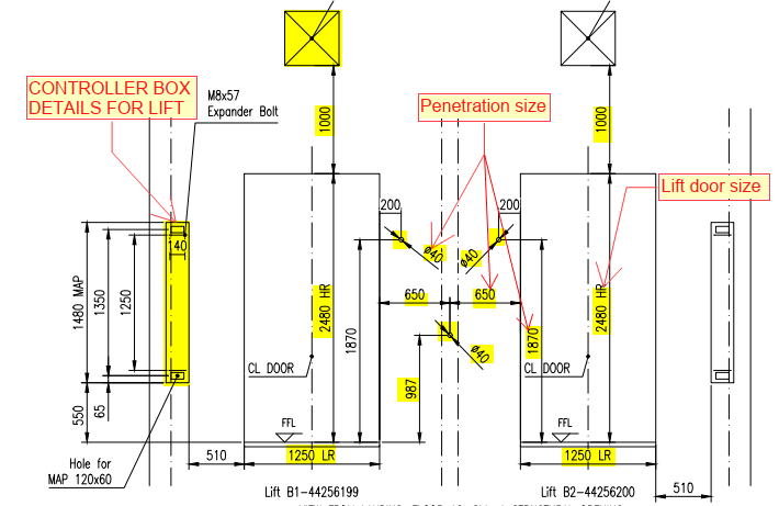
    8. Some cases, the arch core elevations also provided separately for stair and lift. It’s shown the details like door and window set-out, fire penetration set-out, landing slab RL and etc.

    Sample Arch core elevation (Fig.01)

    Sample Arch elevation (Fig.02)

  • TABLE PRECAST FINISHES

    Table precast finishes is the replication process. The surface of the manufacturing table affecting the precast surface. Sometimes the table is covered by form liners, bricks, signage letters & pattern to make the finishes.

    a) Normal table finish:

    Non-exposed surface of the precast is made by this type of table. Same table is used for multiple time for casting the precast. Surface of the table is drilled and nailed for component fixing. Components fixing damages not fixed at every time of repetition, which result poor surface finish.

    b) Good table finish:

    The damaged table surface is being fixed by welding and grinding before every time of casting. Which means each and every time the surface of the precast panel surface will be made well & good.

    c) Form Liner finish:

    custom façade design with architectural concrete, elastic form liners are used to form the finish by placing it on the table before pouring the concreate for the particular design of concrete facades.

    d) Retarder finish:

    It is a type of acid wash, spraying a retarding agent on the surface of the fresh concrete and leaved long time and washed to make aggregate exposed.

    e) Patterned finish:

    As per the Architecture or client requirement various shape of profile needs to make on precast surface by placing the readymade patterns on the table to form.

    f) Brick snap finish:

    Bricks are arranged on the table for required shape before pouring the concrete and demold the panel which has the bricks attached surface of the precast panel.

  • NON-TABLE PRECAST FINISHES

    The finishes are performed without help of table faces. These type of finishes are listed as below…

    a) Float finish:

    Float is a tool used to finish a concrete surface by floating on it. After the concrete is poured on the table is levelled by using screed, then float tool is used. Float may be the small or large handle tool sometimes its powered by engine.

    b) Trowel finish:

    Trowel also a tool used to finish a concrete surface by pushed and pulled across the concrete surface. Trowels are performed in both manual and mechanical types.

    A manual trowel consists of a flat steel blade with an attached handle on top. A Mechanical trowel is used for large commercial projects which have rotational of large fans with the blades directly against the concrete surface.

    c) Polished finish:

    Polished Finish is a multi-step process where a Precast concrete is polished with bonded abrasives or chemicals in order to grind a precast concrete surface. It is then refined with each grind in order to achieve a specified level of appearance.

    d) Broom finish:

    Broom finish of the concrete is rough surface finished made by forcing or dragging a broom on the troweled surface while the concrete is still fresh.

    e) Sand Blast Finish:

    A sandblasted precast panel has a rough finish which is achieved when a precast panel surface is subjected to a high-pressure blast of siliceous sand through an air gun.

  • LIST OF PRECAST FINISHES

    Precast panels are ready made concrete element, which is the part of the building as structural as well as façade panels, which required the surface finish as per the customer or Architect requirements. Various type of finishes are used on the both side of panel and edges according to where the panels are positioned on the building.

    Due to the process of precast manufacturing, the finishes are made by replication of table on the one side, and the other side our traditional or conventional methods are preformed after pouring the concrete. As per concern of precast finishes, its classified as

    1. Non-Table finishes.
    • Float finish.
    • Trowel Finish
    • Polished Finish.
    • Broom Finish.
    • Sand blast finish. etc..

    2. Table Finishes.

    • Normal Table Finish.
    • Good Table Finish.
    • Form liner Finish.
    • Retarder Finish.
    • Patterned Finish.
    • Bricks Snap Finish. etc.
  • UPSTAND Vs CORBEL

    Upstand:
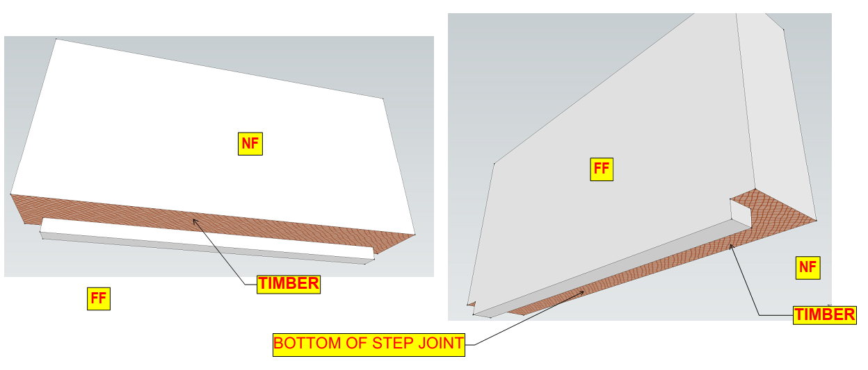
    Upstand is typically used for return legs in a precast element (Panel, Column, Spandrel). Generally, upstand preferred near face in shop drawing. If any special requirement (architectural design) only goes for Far face.
    Because far face is a table face, so we can’t provide upstand on Far face due to manufacturing difficulties.

    Corbel:
    Corbel is typically used for panel thickening increases in a precast element. Its also preferred near face in shop drawing.

    Thickness for Upstand:
    Total length of return value (sum of panel thickness) to be considered as upstand thickness.

    Thickness for Corbel:
    Thickness increase value (Apart from panel thickness) to be considered as corbel thickness.

    Advantages:
    1. The upstand and corbel profile formation used to avoid small size precast elements manufacturing.
    2.And also it will help to avoid some small part of in-situ elements on site.
    3. The construction time will be reduced.
    4. The cost of manufacturing also will be reduced.