

Let us now continue to refactor according to good design principles.
A series of blog posts exploring the Tekla API. Code examples, explanations and (where relevant) videos will be provided.
Let us now continue to refactor according to good design principles.
Ok, so we’ve done some significant refactoring.
We’ve considered a lot of things. Some things still to be improved:
Here is the code thus far:
Ok, that’s certainly a bit better. Still the namining of the classes is quite poor; and we have the dependency inversion issues that we need to fix. Also is there any need to pass in the beams object direction when at the end of the day, we are converting it to a data structure which the printer can understand? Perhaps we should just pass in the printed data structure? We will address these concerns in Part 3 of our refactoring.

We will attempt to do something which is seldom done or discussed in Tekla code samples: and that is the very important issue of refactoring code.
The first thing you need is a good suite of tests. That way you will know whether something has gone wrong or not. It might be tricky doing this since we are developing within the Tekla environment, but I do suppose it’s possible.

WARNING: The code is very dirty. There’s a lot of repetition here. And I’ve gone up some cul de sacs incorrectly. But that’s ok. It’s code which works. We can worry about refactoring for another day – in fact, that will make for a very good exercise. Here is a link to where I document the refactoring process.
I’ll walk you through the code:
Here is the full code unencumbered by commentary:
In the last part we left off having obtained all the bolt distance and placing them in a domain object. In this instalment we will try to export all that data into an Excel Spreadsheet. Please note that the following code is untested – unfortunately there was a lightening storm in Melbourne which short circuited my flux capacitor which means I cannot connect to the TeklaServer – so rather than wait, I thought to get this code out to you.
There are many libraries out there: XLS compatible and not:
The consensus is that the worst of the above is still better than using Microsoft’s office interop dll. If you use that approach, you will need to ensure that MS Office is installed in your deployment machine, and secondly, be sure to dispose of all relevant objects. If you forget, then you’ll be leaking memory. This is a very important point.
* A significant change has been made – we are now filtering the SinglePartDrawings based on: (i) whether they are beams or not and (ii) whether they have the relevant profile – a reader wrote an email asking for this version of the code. I have left the previous version out there as well.
* I’m not an expert with ClosedXML – I just wanted to get the code out there. So it’s a very hackish and non-elegant solution, but I hope it serves to illustrate the point.
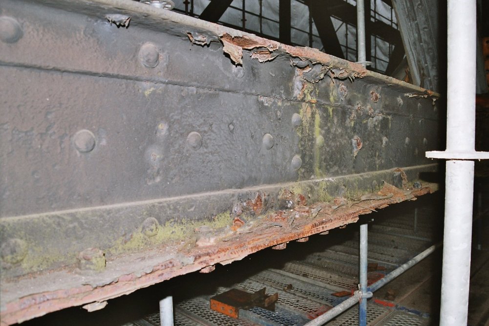
In the last part, we left off having collected the relevant Single Part Drawings that we were after. Hopefully we have applied the correct property to filter out the ‘HEA’, ‘IPE’ and ‘CC’ drawings. We will now focus on part II – extracting the distance of the bolts from the beam’s start position.
I did refactor the code a little bit, so it might not look exactly the same as the last version. The code is pretty self explanatory. But you will note that:
Here is the code in all it’s glory – simply follow the well detailed comments and it should be fairly straightforward. As always, any questions, feel free to ask.
We now have extracted the relevant information. Part III will delve into extracting this data in an Excel format. We will most likely use an OpenXML on other such library for that purpose. That post will come shortly, when I get a spare moment. Till that time, enjoy the following – or perhaps it can be left as an exercise for the user?!
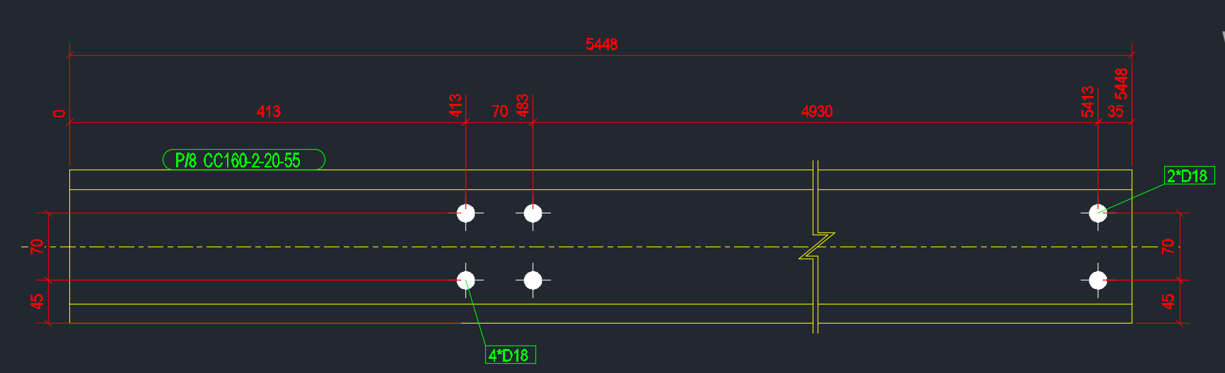
Every now and again we obtain a request from our readership to tackle a problem. If it is of general interest to the public and given our commitments we do sometimes oblige. Here is one such interesting problem. We will tackle this in three parts, and will focus on part 1 in this blog post.
The first part is easy enough – and the code is pretty self-explanatory. We want to iterate through all the drawings and filter for the specific drawings that we are after.
In the next part, we will look at obtaining the relevant parts that we want and calculating the bolt distances from the start and end points. And finally, we will look at refactoring the code, because it is a little slow, and also from a maintainability point of view.
An Addendum

Imagine you are in the Tekla Drawing space.
We want to dimension certain objects in the drawing.
First we need to identify the objects that we want to select. Since the Tekla Closed Open API doesn’t have much of a picker exposed, we would be forced to select the objects we need before running our command. We can do so with a pick first selection (to use the AutoCAD terminology).
The code is quite simple, but is very important:
This is a repost from our sister site – I needn’t repeat it here, but it’s something that I’ve worked on, and which we hope to utilize to a greater degree when working with Tekla. Anyways, you can get the full blog post if you click this link here. Thank you for stopping by.
Select Bolts From Tekla Model Based on its Tolerance using WPF (Tekla Open API) Video Demo from Tek1 on Vimeo.