Industry Foundation Classes (IFC) is an open file format developed by Building Smart Alliance. It is an international data exchange standard for exchanging building information across different software platforms. An IFC Model is just a model of a building or a construction project with all geometric, structural, and semantic information.
Key Features of IFC Models:
Open Standard: IFC is vendor-independent, i.e., any software that supports it can be accessed, without regard for the vendor.
Static Data Exchange: It is mostly utilized for data exchange between software tools, data import, and export. For instance, an architect can create a model using Revit and export it as an IFC file, which can then be imported into structural engineering software like Tekla or SAP2000.
Limitation of Real-Time Coordination: IFC files are representations of the model at a specific moment. Changes in one application are not duplicated in another except where the file is re-exported and re-imported.
Use Cases:
Exchange of models between stakeholders with various software.
Ensuring interoperability in interdisciplinary projects (e.g., construction, engineering, and architecture).
Advantages of IFC Models:
Encourages collaboration and interoperability in BIM workflows.
Reduces errors by making sure all stakeholders are working from the same information.
Allows clash detection and coordination between different disciplines.
B. Live Link Model Viewer
A Live Link Model Viewer is software that enables real-time sharing and visualization of BIM models on various software platforms. Unlike IFC models, which are pre-exported static files, a Live Link Model Viewer enables multiple users to work on the same model at the same time using different software programs. Common examples of Live Link Model Viewers are:
Revit Live: A cloud-based collaboration platform by Autodesk.
Trimble Connect: A BIM data management and sharing tool.
Key Features of Live Link Model Viewers:
Real-Time Collaboration: One software application’s changes are reflected immediately in the model viewer and other linked applications.
Dynamic Data Sharing: Unlike static IFC files, Live Link Model Viewers offer dynamic, real-time linking between software applications.
Multi-User Collaboration: Multiple stakeholders can view and edit one model at the same time even though they are in different software.
Use Cases:
Real-time collaboration among architects, engineers, and contractors.
Collaborative design review and clash detection.
Smooth communication between teams working on different software platforms.
Advantages of Live Link Model Viewer Benefits:
Make collaboration more effective and faster.
Eliminate the need for repeated file imports and exports.
Enhance accuracy by getting the entire team to work on the current version of the model.
It is essential to cross-check the revised consultant drawings we receive against the original drawings from the Quotation stage before commencing the project because this may affect prices.
For example, the panel break up, or the panel specs might have changed. If they have changed, this might have a material impact on price such as concrete and reinforcement cost.
What should we do when they make changes?
Check the consultant drawing revisions and their date (between the quotation and the current stage).
For example:
2. Highlight the changes that occurred and mark them down in the latest structural PDF.
For Example:
3. Prepare a summary document report outlining the modifications.
For Example:
4. Inform the precast manufacturer and builder about these changes by sending the relevant information via email.
For Example:
Why do we need to check the consultant drawings?
This verification process will enable the precast manufacturer and builder to re-evaluate the timeline based on the information that was previously quoted. This allows potential Cost issues that could cause confusion or delays in the project timeline to be identified and resolved early on such as
Cost estimation of individual precast panels, including their respective panel areas and concrete volumes, for manufacture.
Cost estimation of approximate reinforcement and mesh weight requirements.
List of cast-in items and loose items required, approximate quantities.
What are the key factors that need to be verified in the consultant drawings from a precast perspective?
Panel Thickness and Types: Verify the panel thickness and types used, as specified in the Structural Drawings.
2. Panel Count: Confirm the panel count based on the panel split, as detailed in the Structural Drawings.
3. Panel Transportability and Tonnage: Conduct a transportability check and verify the tonnage of the panels from our end.
4. Panel Reinforcement:
Perimeter bar diameter
Mesh type used and its placement
Additional reinforcement provided in the panel typical detail
Reinforcement on central or either side ( specify location) (Refer to Structural Drawings for details)
5. Precast Wall Pattern and Special Moulds: Verify the precast wall pattern and special moulds required, as specified in the Architectural Drawings.
6. Panel Finish: Confirm the panel finish, as specified in the Architectural Drawings.
7. Panel Connection Details: Verify the panel connection details, if applicable, as specified in the Structural Drawings
We were having trouble with Precast jobs which involved Brick Snaps. We estimated that it would take +100 hours. Most of the time is pure manual labour – which could be automated, provided you worked out where / how.
We found that splitting bricks along panel lines and curves were taking inordinate amounts of time. A tool was developed and here it is.
Refer crane drawings for loading platform location, Crane tonnage & its relevant circles and other crane related data’s. (Refer Fig.01)
Fig .01 (Ref. Crane drawing)
2. Lift drawings
Refer these drawings for lift door opening size & set-out, lift door fitment rebates, landing RL’s, penetrations and rebates for call buttons & indicators, service hatch openings, Unistrut’s locations, lifting eye locations and loading factors, switch cut-out on final floor and other lift related data. (Refer Fig.02)
Fig .02 (Ref. Lift door & penetration details)
3. PT drawings
Must refer these drawings for PT tendons passage location. Wherever the PT tendons passing through the precast we must provide block-outs to suit accordingly. The nominal size of block-outs for PT to pass through as per engineer requirements. If not shown on any drawings, we need to raise RFI (Request for information). (Refer Fig.03)
Fig .03 (Ref. Post tension drawing- PT)
4. Mechanical service drawings
Refer these drawings for mechanical openings in slabs & walls. Mainly for duct works, garbage chutes, kitchen exhaust chutes, stair pressurization openings, etc. (Refer Fig.04)
Fig .04 (Ref. Mechanical service drawing)
5. Electrical service drawings
Refer these drawings for electrical penetration requirements in slabs & walls. Mainly for communication, power and other electrical related accessories to pass through. (Refer Fig.05)
Fig .05 (Ref. Electrical service drawing)
6. Fire service drawings
Refer these drawings for Fire service penetration requirements in slabs & walls. Mainly for fire hydrants, sprinkler system and its pipe accessories to pass through. (Refer Fig.06)
Fig .06 (Ref. Fire penetration drawing)
7. Steel detail drawings
Refer these drawings for Steel to precast connection details. Mostly if some connection like this present, we will get intimated beforehand. (Refer Fig.07)
Fig .07 (Ref. Steel drawing)
8. Hydraulic service drawings
Refer these drawings for Hydraulic service penetration requirements in slabs & walls. (Refer Fig.08)
In-situ or Precast element present above the door or window opening is called header. (Ref.Fig.01&02)
Usually, the height of header will be small, and it will have more load impact for the smaller load distribution area.
For structural stability that header needs to have high strength. If structural engineer didn’t specify more strength means it won’t have higher load distribution impact. So, that area requires more reinforcements. (Ref.Fig.03)
Structure engineer drawings specifies that detail in separate header beam detail or in core elevation drawing or even in nominal elevation or as a separate document as per the need and availability.
While providing reinforcement arrangement for header, we need to consider room space on header beam. So, for header reinforcement arrangement we need to the arrangement in 1:1 scale to ensure that no complication & difficulty will arise in factory as well as site.
If any penetration comes at header which is larger in size than for ties spacing, we need to add two ties at both sides of penetrations.
We need to raise RFI (Request for information), if header reinforcement details not provided by structural engineers.
Grout Tubes are hollow components and are made of plastic or thin sheet metals. (Refer Fig.01)
Grout tubes are cast into precast elements which create a void to locate and connect the elements (between two precast elements or in-situ to precast elements) together using starter bars or dowel bars.
Once the elements are in position, the grout tubes are filled with grouting material and locking the elements in position.
Fig.01 (Sample bottom Grout tube with breather)
Purpose of Grout tubes:
Grout tubes are used in the construction of precast concrete buildings for connecting elements like walls, tilt-up panels, beams, columns, etc.
It will help to increase the strength and durability of the precast or in-situ elements.
General details for Grout tubes
Hollow components with spiral designs or key ways in its walls
Selection of grout tubes based on dowel size
Alternatively, NMB splice sleeves or penetrations can be used or dowel bars can be directly casted if having rebar’s arrangement congestion
Grouting materials must be filled for Load bearing areas and voids will be present for NLB (Non load bearing) portions.
Must not clash with other components in precast (Cast in plate, Lifter, Lig-cage, lig-cage hooks, Prop, Grooves, Ferrules and etc.) – Refer Fig.02
Face of breather must be inside of building and must have access, must not be placed where sequential grooves or architect patterns present.
If breather has no access must provide breather extent to where the access is possible (not required when it is NLB)
Must have a minimum gap of 200mm with other components especially lifters & block-outs (this value can be modified, if having difficulties to maintain that gap)
Avoid the Grout tube placement near to window & major openings (wherever possible)
Grout tube must be placed within 300mm from panel edge. (But can be modified if having any difficulties.)
Fig.02 (Sample Top Grout tubes)
Advantages:
Lightweight and easy to process
Available in a range of sizes
It will help to reduce the construction time on site
Easy to connect with precast or in-situ elements
Disadvantages:
The huge amount of grout tubes needed to fill up the duct in order to secure the connection between the precast wall or in-situ.
Dowels are short straight steel bars and also cogged bars, used to provide mechanical or structural connection between two precast elements or in-situ to precast elements. (Refer Fig.01)
(Fig.01) Dowel bars
Purpose of Dowel bars:
Dowel bars used to maintain the horizontal and vertical alignments of slab and precast panel. (Ref Fig.02)
Dowel bar connection used to transfer the loads between two concrete elements or two precast elements or precast to in-situ elements. (Refer Fig.03&04)
Dowel bar is used to extend the structure easily with small drilling to insert the steel for the extension of the structure.
General details for Dowels:
Dowel bar is a steel rods with spiral outer design. (Refer Fig.01)
Used in all the locations where Grout tubes are required.
Selection of Dowel based on Engineer requirement.
Dowel can either be black finish or galvanized finish.
Black finish for load bearing dowels and galvanized finish for NLB (non-load bearing) dowel. (It may be varied).
Alternatively, bars connected into NMB splice sleeves can be used. Also, starter bars can be casted into panel.
Plastic tube will be placed over upper half of dowel. And 20mm compressible cap will be placed over the top of the dowel bar for NLB (non-load bearing) portions whereas grouting material will cover the entire dowels for LB (Load bearing) conditions.
Dowels must be positioned within Grout Tubes with minimum amount of clearance on precast walls or slabs.
Advantages:
It is reducing the corner cracking.
It will reduce joint faulting.
Dowel bar is also used to reduce the deflection and stress.
Core plan shows the core wall, shear wall and overall slab boundary. (Only if it is provided by separate structural engineer specifically working for cores & shear walls).
Also, it’s shown the elevation number and viewing direction. (Only if it is provided by separate structural engineer specifically working for cores & shear walls) – Refer Fig 01.
Precast legends will be provided at title sheet.
If too many building means, they highlighted the site key plan with current building.
For single building area of working, they provided the key plan with elevation numbers and views. (Only if it is provided by separate structural engineer specifically working for cores & shear walls).
In Core/Shear walls elevation, concerned engineer will provide below details – Refer Fig 02
Dowel bar requirement
Tension bar requirement
Thickness of panel
Grade of panel
Reinforcement requirement (in some cases it will be given in a separate sheet)
CIP requirement
Wet-joint details (usually wet joint only specified. Brief details will be given in separate sheet)
Header detail schedule type (in some cases header type only given, and will be defined in another sheet)
In core elevation and plan, we prefer to give more importance to elevation than plan, if any issue in it we can raise RFI (Before raising RFI we have to completely analyses the discrepancy, and make a call inward and finalize the deviation. If it is not finalized then only, we can raise RFI (Request for information).
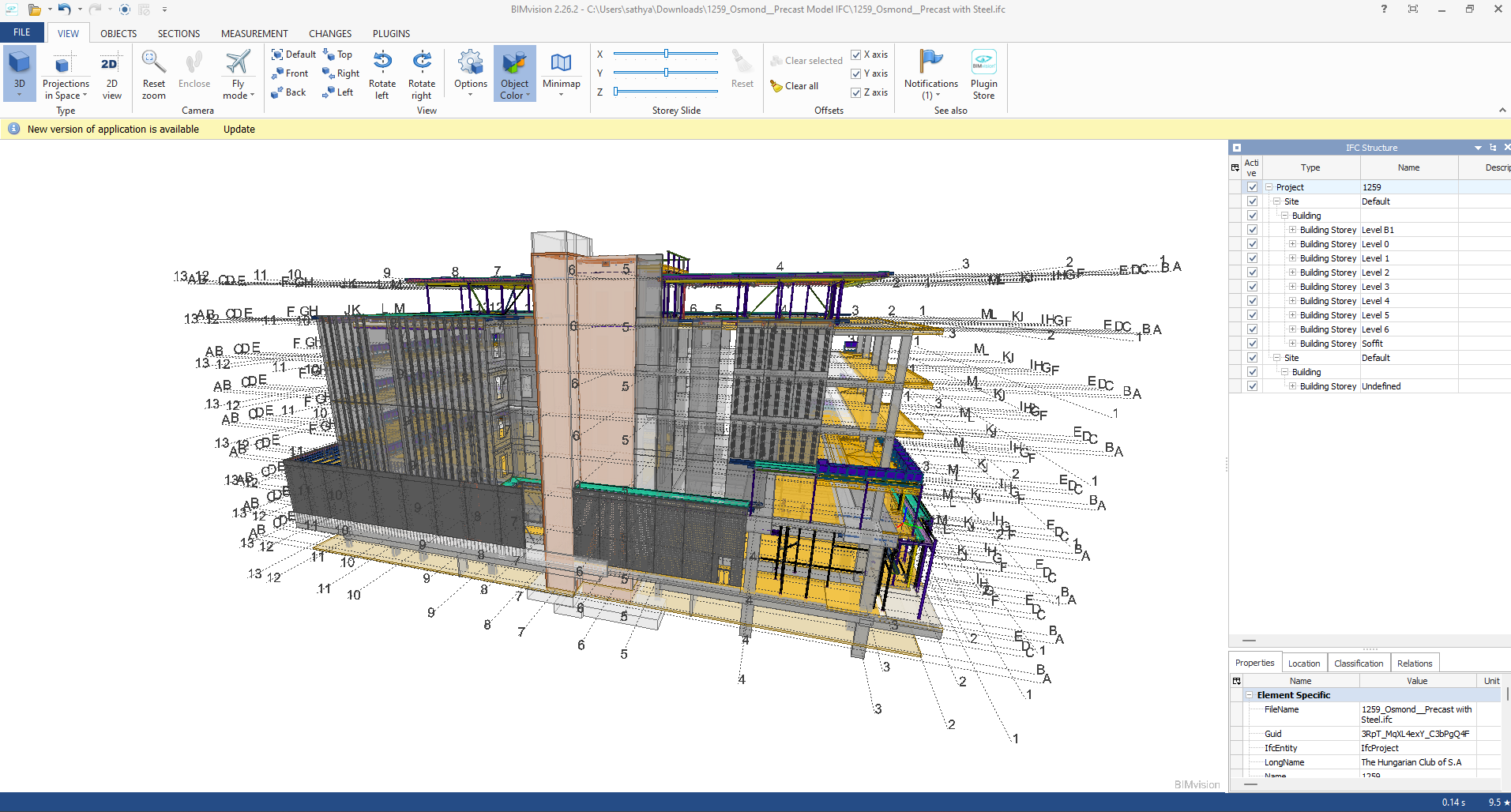
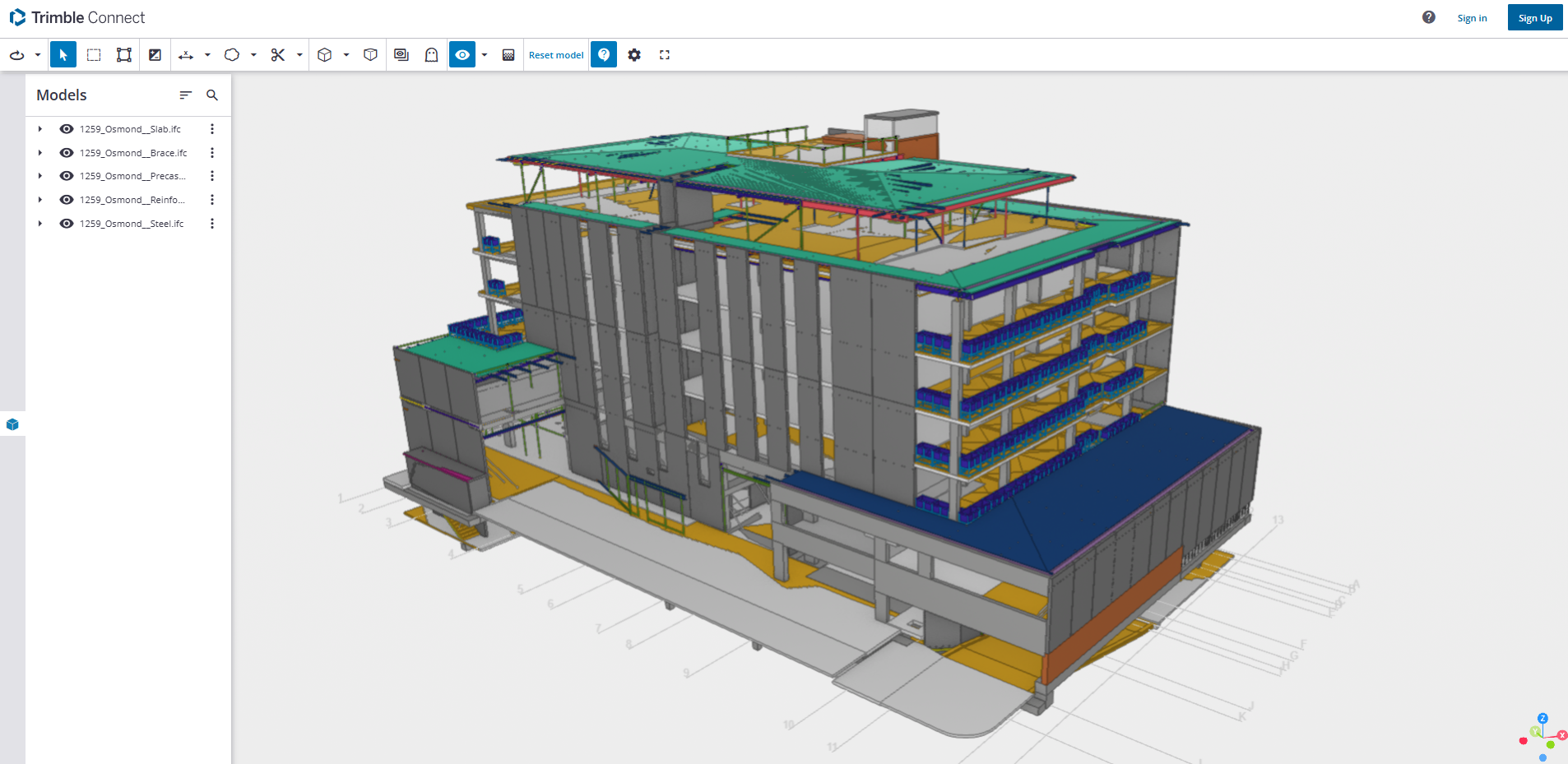
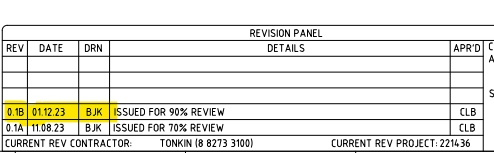
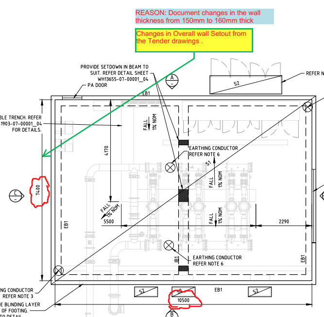
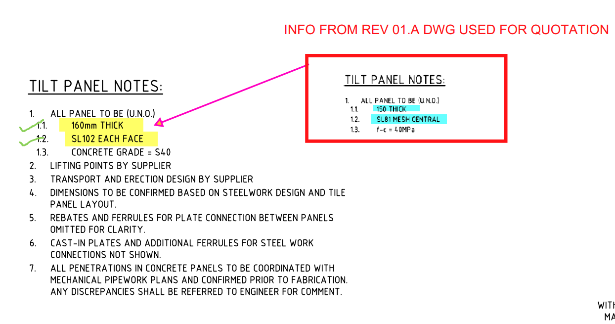
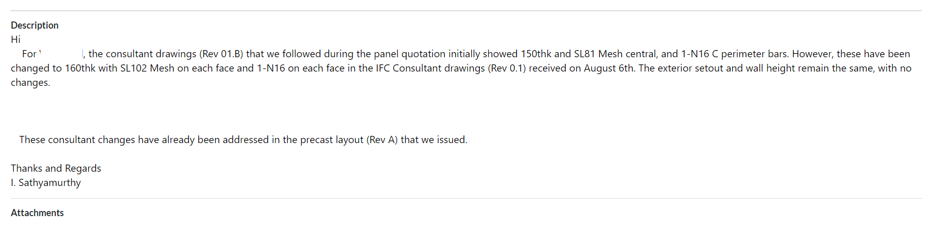
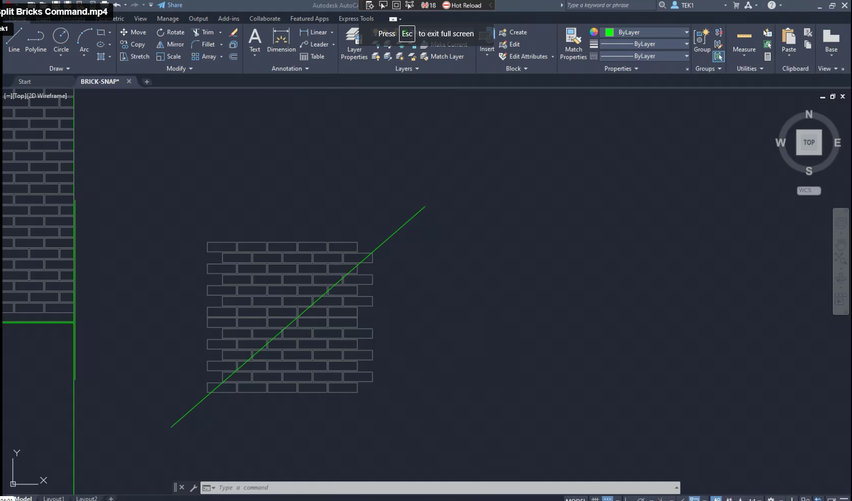
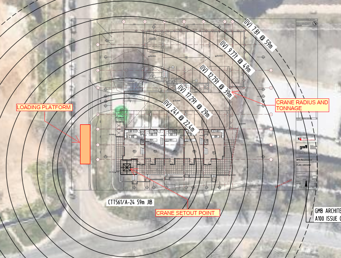
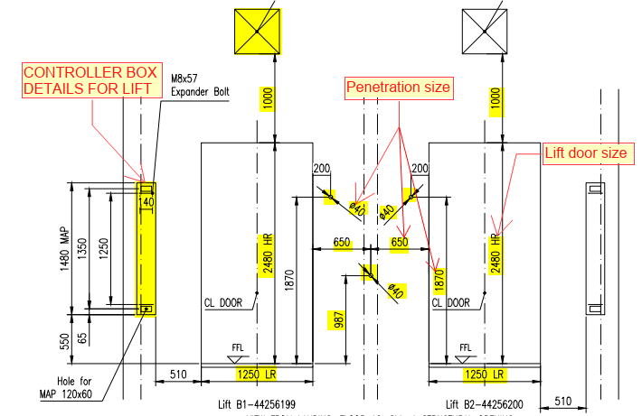
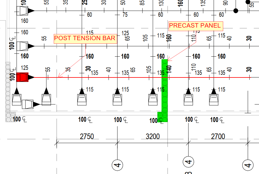
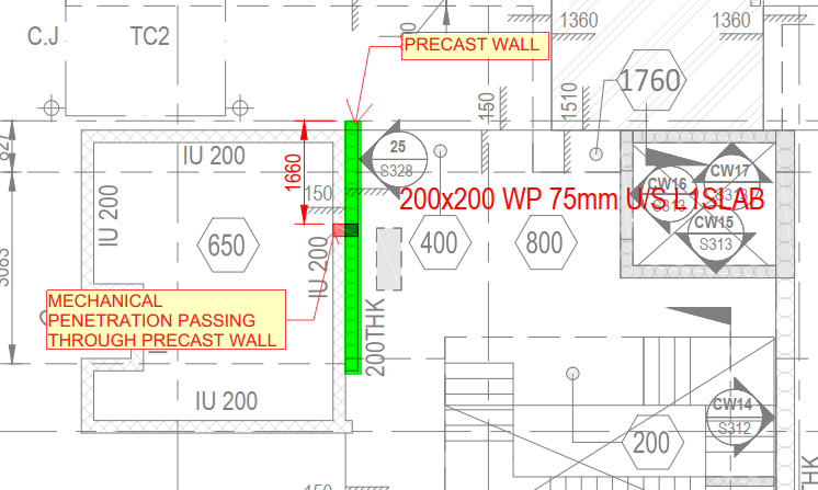
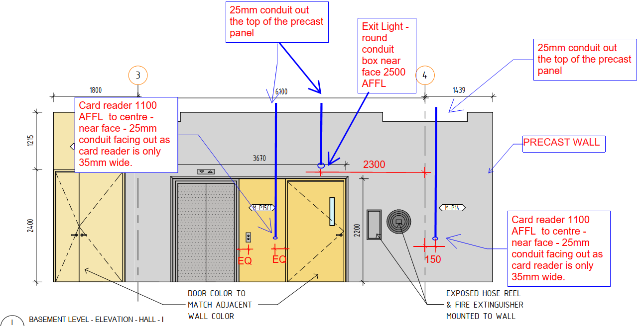
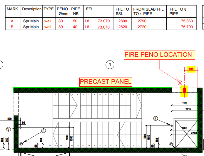
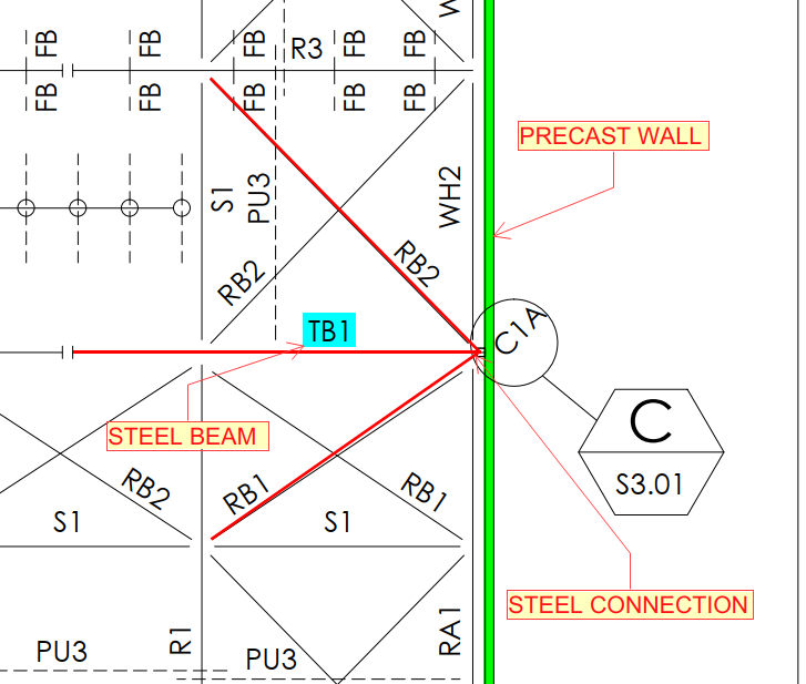
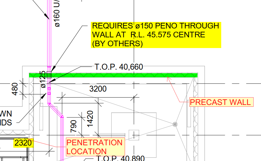
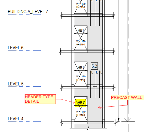
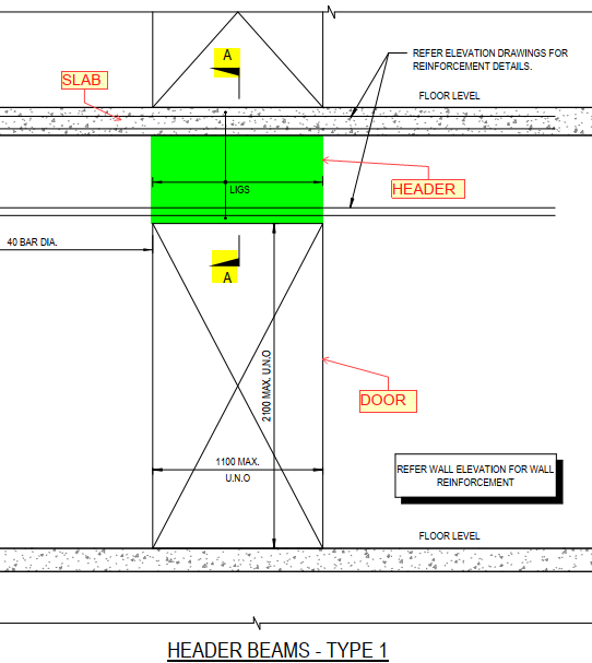
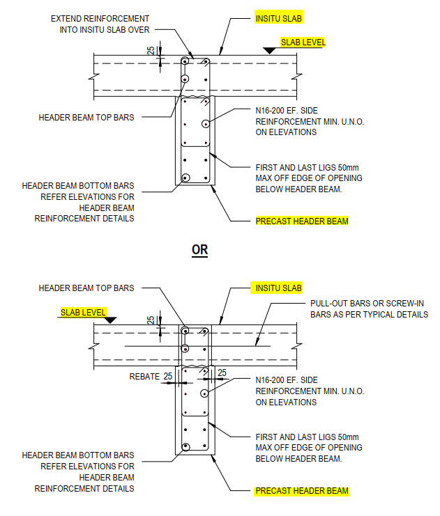
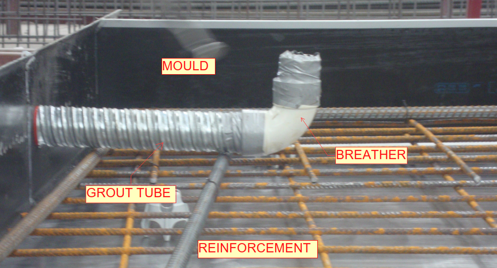 Fig.01 (Sample bottom Grout tube with breather)
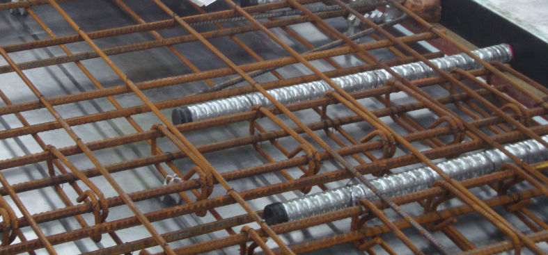 Fig.02 (Sample Top Grout tubes)
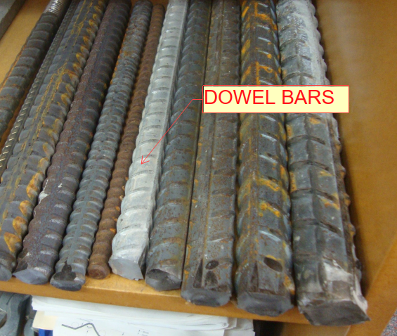
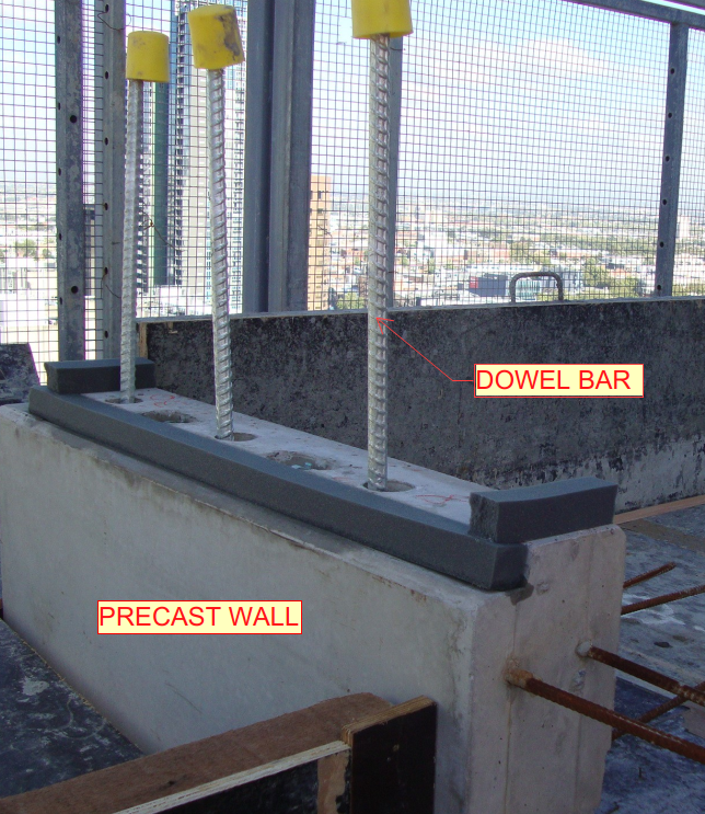 (Fig.02) Precast wall connection
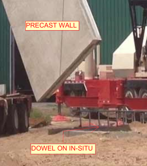 (Fig.03) – Precast to in-situ connection
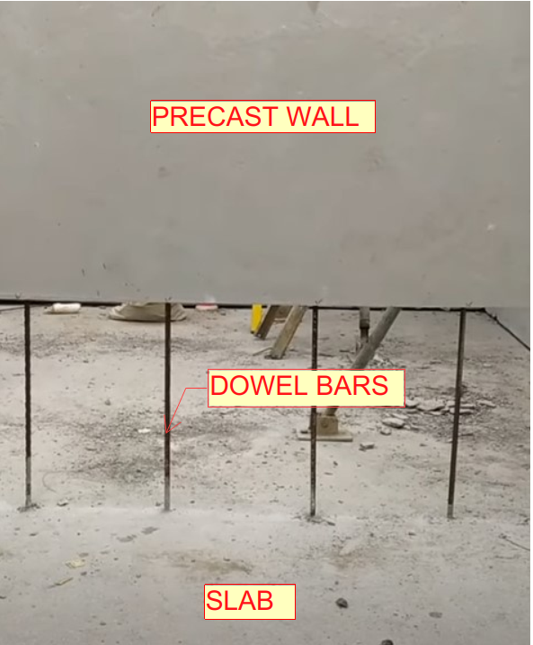 (Fig.04) – Precast to slab connection
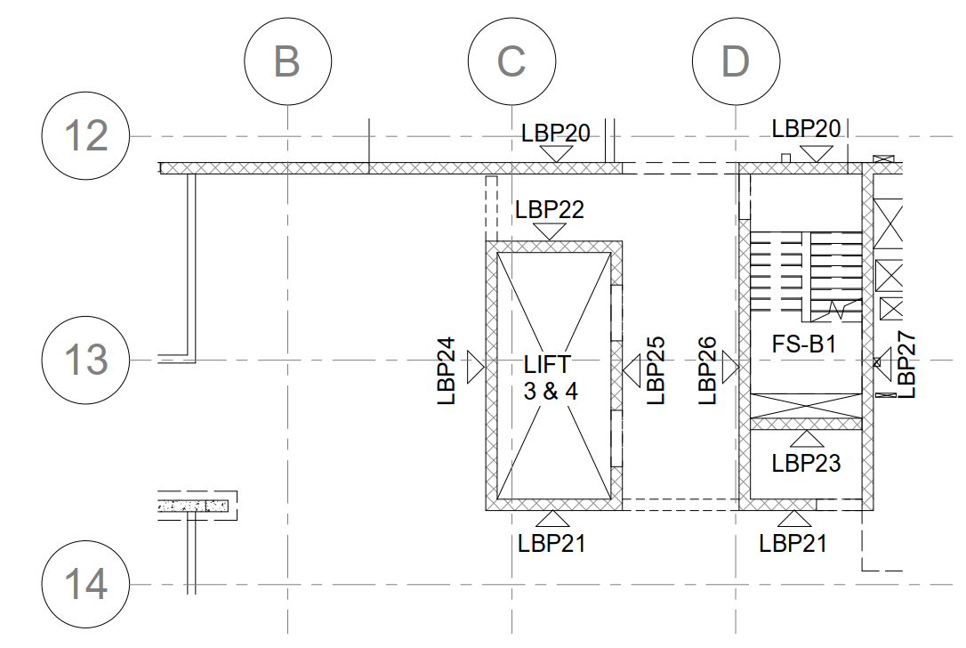 (Fig.01) SAMPLE CORE KEY PLAN
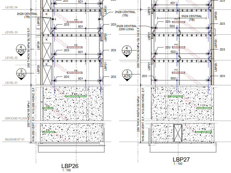 (Fig.02) SAMPLE CORE ELEVATION