General Details about table:
- Tables are used for fabrication of precast panels in factories or yards with good quality, finish, curing and low time consumption.
- Different types of materials used for tables like timber, aluminum and steel. But steel is mainly used for tables because it’s good for repetitions, gives good vibration to concrete, it’s not easily damaged and tables do not expand when it’s wet, etc.
- The cleaning process is also easily done for steel tables with the help of air blowing or cotton waste.
- In the yard there are different types of tables used for fabrication.
For example normal fabrication tables and tilt up tables.
Normal table:
- Normal tables are mainly used to fabricate most of the precast panels.
(Refer Fig 1)
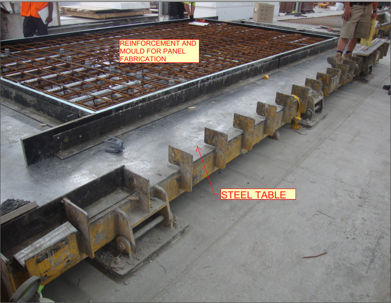
Fig 1
- Advantages:
- Normal tables will not take more manpower for cleaning and fabrication of precast panels.
- The maintenance is easy
- The cost is low when compared to other types of table.
- It can easily fix where we need to fabricate the panels.
- It will be fixed on the floor, so the visibility of the table is good for all.
- Disadvantages:
- It’s not suitable for doors or big opening panels. Because in case of lifting panels it may break.
- Normal table needs additional lifting support.
Tilt up table:
- The tilt up tables are mainly used for Doors and big opening panels and also other types of panels. (Refer Fig 2 & 3)
- The tilting process allows the precast concrete element to be removed safely and without damaging it.
- The titling tables are designed in particular for mobile use and can be quickly transported from the yard.
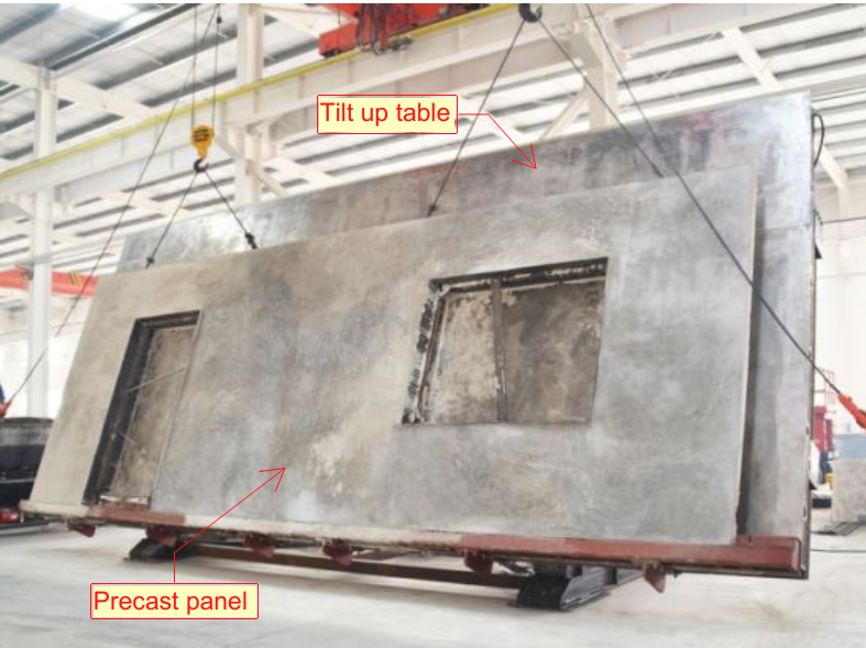
Fig 2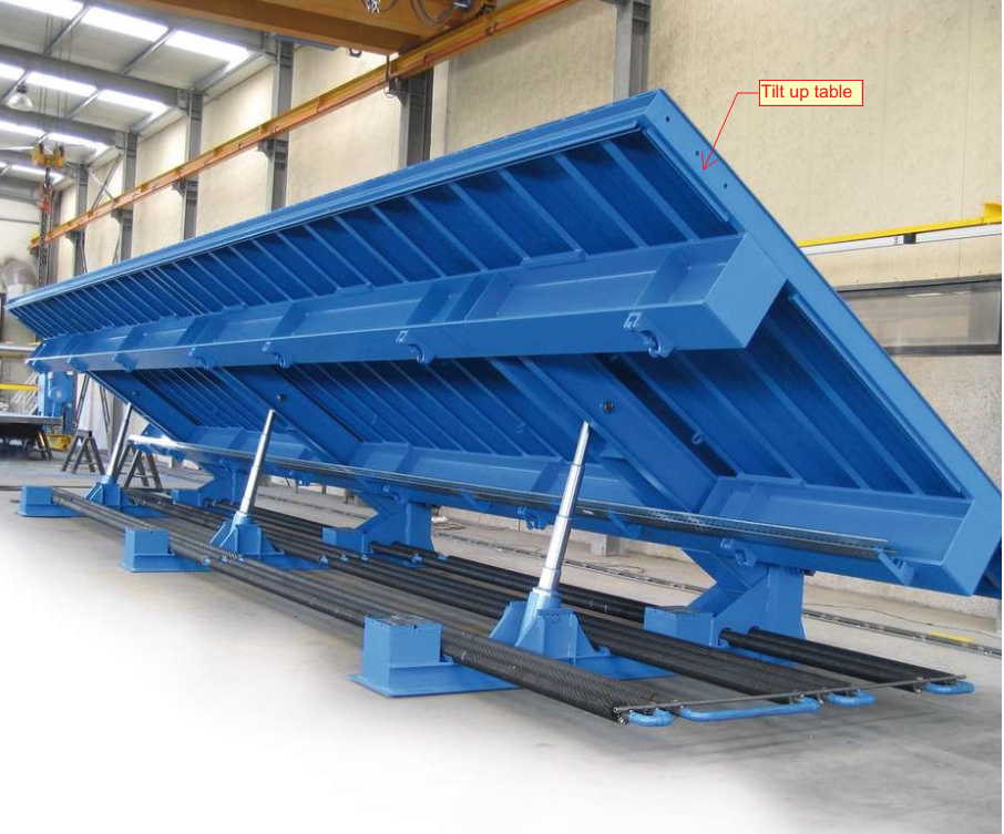
Fig 3 - Advantages:
- This table is good for fabricating and lifting the door, opening type of panels.
- Hydraulic Tilt up Tables reduce manufacturing time because it’s not require more pouring time to lift the panel from table.
- Vibration technology based operation ensures qualitative compaction of concrete and a consistency in quality.
- It’s very high level of concrete compacting with low noise.
- Minimal costs when transporting the tilt up table.
- Disadvantages:
- Manpower is necessary and also needs knowledgeable people for handling.
- The maintenance is difficult
- The cost is high
- It’s not movable, so we need to collect materials at a nearby table.