Category: General Tips

  • Post tension Tendons Passing in Precast Panel

    Subject: Things to do when we have post-tensioning cables passing through precast panels

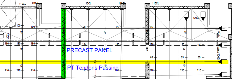
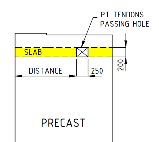
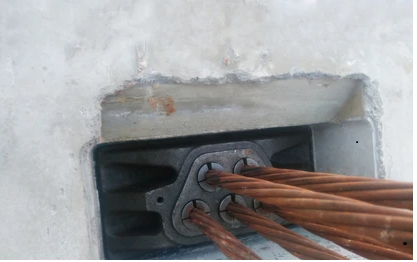
    If we have both post-tensioning slabs in the location of precast, we have to provide a block-out hole in the precast to pass the tendons through the precast.

    What we care to take when detailing precast panel.

    We have to provide an opening in the panel for PT cables to pass through. Do not place any precast hardware closer than 100 mm from the hole/block-out.

    How it looks

  • DEMOULDING SLOPE

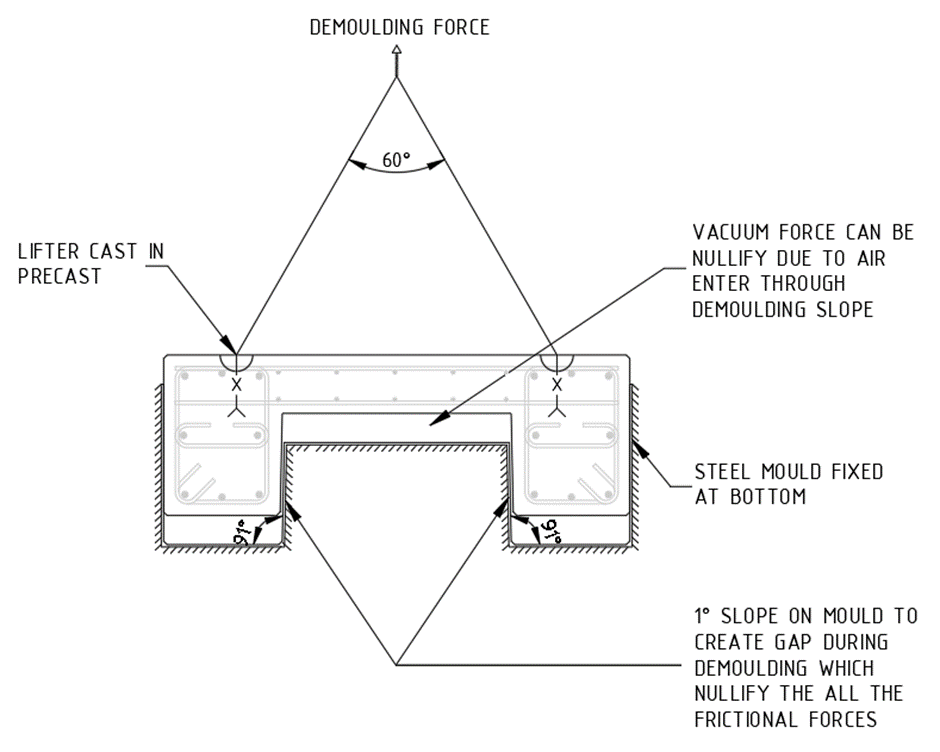
    Demoulding of precast member without damage to either the components like lifter or mould is critical to successful replication process for the particular complicated design. During mould design, the designers concentrate to make minimum draft (nearly 10 ) on mould to wherever the possible  to minimize demoulding force and resultant stress on lifters and prevent on weaker part of the precast member.

    For Example,

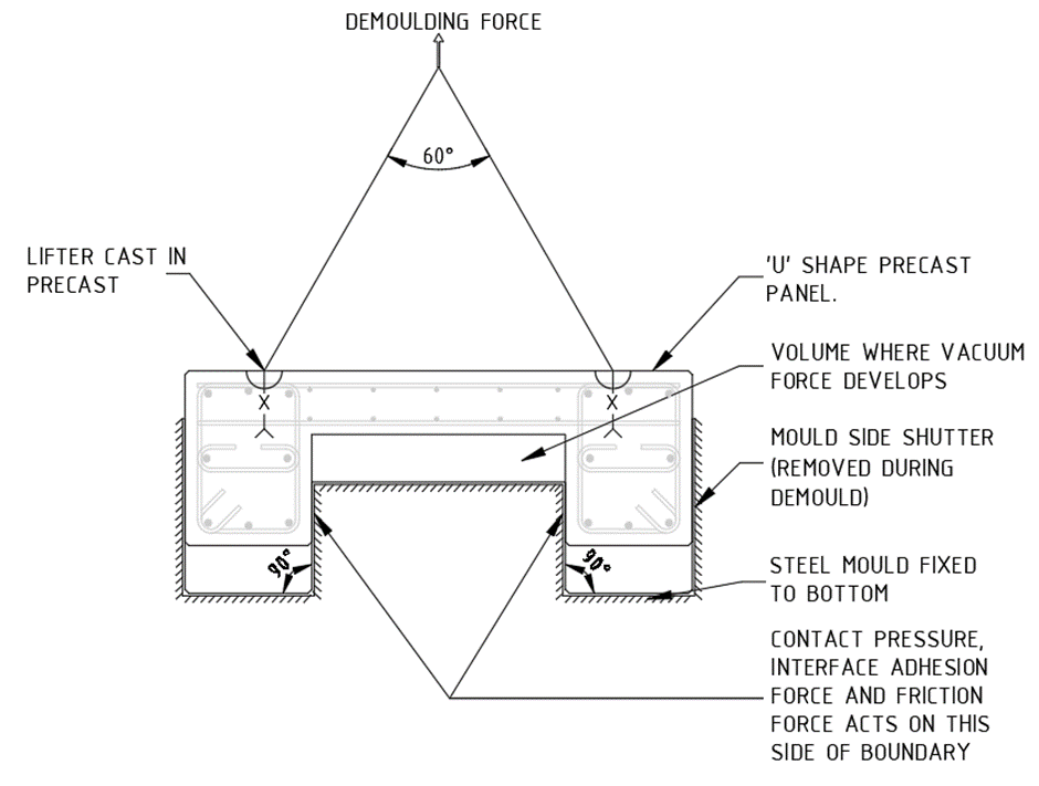
    CONTRIBUTORS DURING DEMOULDING WITHOUT SLOPE

    The above picture shows influencing factors for demoulding force. In this case the resultant DEMOULDING forces like vacuum & friction (Area of contact, Coefficient of friction & Normal contact Pressure) along with self-weight of precast will increase demoulding force. If the demoulding force exceed the lifter capacity limit leads to fail the lifters. So, we can’t able to lift this precast member. To eliminate this type of failure. We need to provide slope where contact pressure or interface adhesion develop.

    CONTRIBUTORS DURING DEMOULDING WITH SLOPE

    The above picture shows the effect of demoulding slope. Where the 10 slope didn’t affect too much the original shape of precast, but considerably minimize the demoulding force. The slope reduces the frictional force & provide passage to air enter where vacuum force develops.

  • CONCRETE WITH SPECIFICATION DIFFERENCE (N & S)

    CONCRETE:

     (AS 1379 Specification and supply of concrete) A mixture of Cement, aggregates and water with or without the addition of chemical admixtures or other materials.      

    Cement: (AS 3972 Portland or blended cement) A hydraulic binder composed of Portland or blended cement used alone or in combination with one or more supplementary cementitious materials.

    Concrete is defined as follows,

    • Plastic concrete:

    Concrete in the state between completion of mixing and initial set as defined in AS 1012.18 Methods of determining setting time of fresh concrete, mortar and grout by penetration resistance.

    • Hardened concrete:

    Concrete after initial set, as represented by test specimens that have been subjected to a specified process and duration of curing.

    • Normal- Class Concrete:

    Concrete that is specified primarily by a standard compressive strength grade up to 50 MPa and otherwise in accordance with Clause 1.5.3.

    • Special- Class Concrete:

    Concrete that is specified to have certain properties or characteristics different from, or additional to, those of normal-class concrete and otherwise in accordance with Clause 1.5.4.

    SPECIFICATION OF CONCRETE:

    Concrete shall be specified,

    (a) as either

    (1) Normal-class(N), or

    (2) Special-class(S), or

    (b) By strength grade or other readily verifiable parameter by which compliance with the specification can be assessed.

    NOTE: Standard strength grades should be specified wherever possible.

    • NORMAL-CLASS CONCRETE:

    Normal-class concrete shall be specified only by the parameters given in Clause 1.5.3.2(Basic parameter), and shall have the following attributes:

    • A mass per unit volume in the range 2100 kg/m3 to 2800 kg/m3 when determined in accordance with (AS 1012.12.1 Determination of mass per unit volume of hardened concrete) in the saturated, surface-dry condition.
    • Acid-soluble chloride and sulfate contents within the limits given in Clause 2.7, when determined in accordance with Clause 5.5.2.
    • A shrinkage strain not exceeding 1000 × 10−6, when determined in accordance with Clause 5.6 after 56 days drying.

    NOTE: This maximum value of 1000 × 10−6 is consistent with the use for design purposes of a median basic shrinkage strain value of 850 × 10−6.

    • A mean compressive strength at 7 days, assessed in accordance with Clause 5.7, of not less than the values of Grade designation for N20-9MPa, N25-12MPa, N32-16MPa, N40-20MPa & N50-25MPa.
    • A cement complying with (AS 3972 Portland or blended cement) alone or in combination with one or more supplementary cementitious materials.
    • No lightweight aggregate as defined in AS 2758.1 Aggregates and rock for engineering purposes Concrete aggregates.

    Basic parameters of normal-class concrete:

    The following basic parameters shall be specified by the customer:

    • A standard strength grade selected from 20MPa,25MPa,32MPa,40MPa, 50MPa,65MPa,80MPa or 100MPa and designated as one of N20, N25, N32, N40 or N50.
    • The slump at the point of acceptance, selected as one of 20 mm, 30 mm, 40 mm, 50 mm, 60 mm, 70 mm, 80 mm, 90 mm, 100 mm, 110 mm or 120 mm.

    NOTES:

    1. The customer should carefully consider that the specified slump of concrete suits the placement method.
    2. For residential slabs and footings, if the slump is not specified by the customer, the specified slump should be considered to be 100 mm.
    3. The maximum nominal size of aggregate, selected as one of 10 mm, 14 mm or 20 mm. Unless otherwise specified, the default value shall be taken as 20 mm.
    4. The intended method of placement, including relevant details of equipment.
    5. If project assessment is required to be carried out by the supplier (see Note).

    NOTE: If unspecified, it will be assumed that project assessment is not required.

    • If required, a level of air entrainment up to a maximum of 5.0%.

    (2) SPECIAL- CLASS CONCRETE:

    Concrete other than normal-class concrete shall be specified by the customer as specialclass and, if applicable, by strength-grade. The parameters and attributes that should be specified for special-class concrete should be as set out listed below with reference to Appendix B and Table B1 on AS1379.

    Special-class concrete commonly has the same basic parameters as normal-class concrete with some additions and(or) exceptions. Parameters or attributes that are different from, or additional to, those of normal-class concrete should be included in specification below. If the requirements of specification for any concrete are inconsistent with those for normal-class concrete then the requirements of specification take precedence for that concrete.

    Where any parameter other than strength grade requires the specification of a special-class concrete, or the proportions of the mix are specified, the concrete should be identified by an appropriate code agreed to between the supplier and customer that identifies that particular mix.

    Basic parameter for specification of special-class concrete:

    • It is recommended to select from standard strength grades of S20, S25, S32, S40, S50, S65, S80 and S100.
    • Where concrete is specified as special-class and a strength grade is applicable, the strength grade is designated by the prefix:

    S, for compressive strength grades;

    SF, for flexural strength grades; or

    ST, for indirect-tensile strength grades.

    Where concrete is special-class and any property other than strength grade is Specified as the principal criterion, or the proportions of the mix are specified, it is designated by an appropriate alphanumeric code, agreed between the supplier and the customer, to indicate the criterion.

    • Special-class concrete should be subject to project assessment.
    • Certain concrete exposure classifications may require special provisions for aggregate durability (AS 2758.1 Aggregate & Rock for engineering Purposes.)
    • Any departures from the parameters or composition, or both, of normal-class concrete and any other criteria or limitations shall be specified by the customer in consultation with the supplier.

    NOTE: A summary list of several such parameters, some or all of which may be specified for the production of special-class concrete for a project, is given in Appendix B on AS 1379.

    • Other requirements additional to these parameters may be specified.

  • CONSIDERATRIONS-LIFT SHOP DRAWINGS FOR PRECAST

    The important things to be considered in lift shop drawings for precast is listed below:

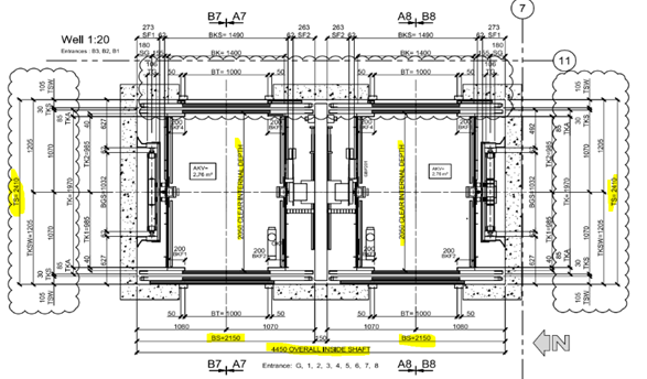
    1. Core Setout.
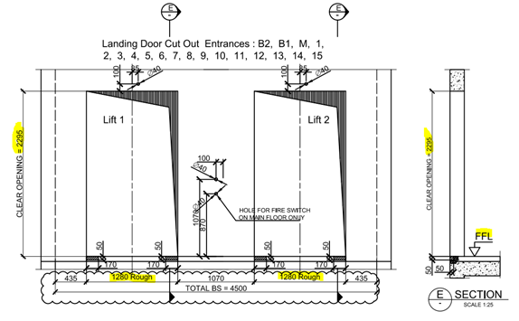
    2. Door Opening.
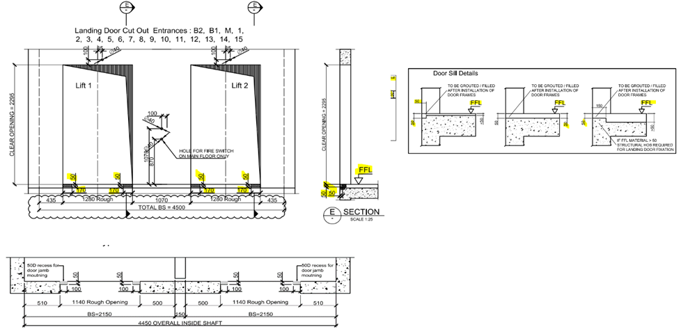
    3. Recess at the bottom of lift door.
    4. Landing Call Buttons penetrations.
    5. Controller Box Penetrations.
    6. Service Penetrations and internal platform box.
    7. Lifting Eye Placements & capacity.

         1. CORE SETOUT:

    1. Lift Core Panels Setout in Concrete plan and structural plan should match with lift core details.
    2. If any thickness of panels change keep inside dimensions unchanged, because inside dimensions are dictated by lift manufacturer’s drawings. Panels thickness change must affect only the outside dimensions of lift core.
    3. Propping method – Lift Cores are generally erected first. Higher level slab may not have been poured when lift core goes up. Hence propping of lift core need to have some special attention.

    2. DOOR OPENING:

    1. The door opening width and height of lift in lift drawing should match with architect and structural drawings.
    2. Make sure that the height of lift door opening in lift drawing are measured from FFL or SSL.
    3. Minimum Header height should maintained Discuss with interested parities if there any doubt.
    4. Always consider the RL’s difference between FFL and SSL while  the opening height are finalized. FFL and SSL are usually different

    3. RECESS AT THE BOTTOM OF LIFT DOOR:

    1. The recess at the bottom of lift door (as per door sill detail) is provided for door frame installation. Make sure we take this into consideration
    2. The door sill details are not same for all projects we need to confirm the depth and width of recess at the bottom of lift door before start the detailing.
    3. If the door sill height recess is wrongly provided (i.e. Measured from SSL instead of FFL) then there will be a problem in installation of lift door frame.
    4. The provided recess depth should start from the end of clear opening of lift door.
    5. Make sure that the Door sill details provided in lift drawings are measured from FFL or SSL.

    4. LANDING CALL BUTTONS PENETRATIONS:

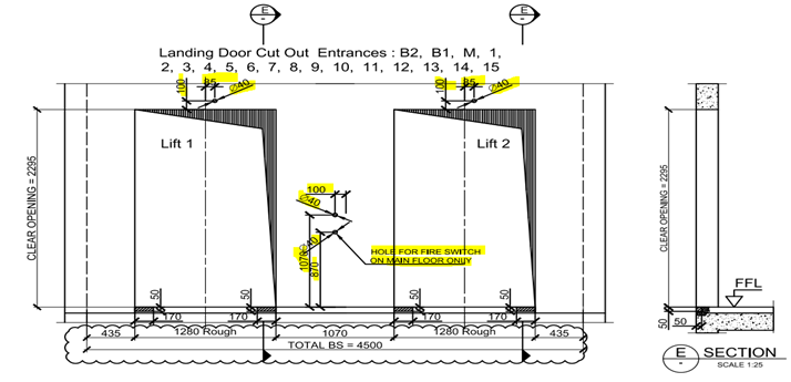
    1. Penetrations for landing call buttons, fire switch and other electrical purpose are to be placed as per lift manufacturer’s drawings.
    2. First confirm the view direction of lift drawing (viewed from landing i.e. Outside) and precast Setout. It will clear the location of the lift call buttons and other penetrations.
    3. Ensure the height of penetrations provided in lift drawings are measured from FFL or SSL.
    4. There will be penetrations of different diameter according to its purpose i.e. call buttons, electrical, fire switch etc. so concentrate more on size and location of penetration while detailing.
    5. Penetration locations and size may vary according to the respective floor entrances so refer the details from correct floor entrance which is given in lift drawings.  

    5.CONTROLLER BOX PENETRATIONS:

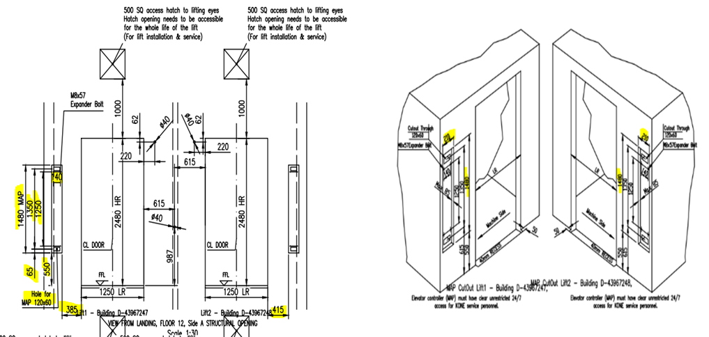
    1. Controller box may need a recess or in some cases could be a penetration.
    2. Ensure the location of the control box from the panel edge, we need to maintain the sufficient gap from the edge of the panel.
    3. Ensure the sufficient cover from reinforcement with the penetrations

    6. SERVICE PENETRATIONS AND INTERNAL PLATFORM BOX:

    1. Ensure the Hatch opening / exhaust opening need to be accessible for the whole lift for installation & service.
    2. In some case there will be an internal recess requirement to allow for attaching temporary platforms inside the lift for servicing the lift. Make sure these recesses are same RL and opposite.

        7. LIFTING EYE PLACEMENTS & CAPACITY.:

                 For the whole lift is closed by 2 types of lids One by cast-insitu lid and another by precast lid. If we have the precast lid, we need to consider the following things

    1. Connection between the vertical precast & lid
    2. Slope for the water drain
    3. Finish of the face of the lid
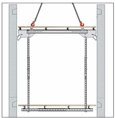
    4. Lifting Eye & Hooks for the Lift car & accessories fixing
    5. Ensure the Capacity & size of the Hooks from the lift design.

  • Stair & Platforms – AS1428 & AS1657 – Online Training, Standards, Codes and Tests

    Applicable stairs, and ladders require compliance to:

    • AS1657 standards (by law in most Australian states – Victoria being the exception) – (sorry I can’t source the original copy here because it cost me $500)

    How can you test whether you know the standard? Take our online test – all detailers must pass this before they are allowed to detail any stair.

    Contact us for your detailing requirements.

  • Does it Fit? An Example of an Erection feasibility check against particular steel profiles (Detailing Tips: No. 1)

    As a detailer, we should constantly inspect and second guess the drawings and the details given to us by engineers and architects (well, mostly architects, because as a general rule, engineers are competent).

    The Pop-Quiz

    If you wish to engage in a pop-quiz: see the drawing attached here: Spigot Connection. What problems can you see arising if you follow the details put forward. The answers are contained below. Scroll down If you wish to see them.


    Scroll down for the answers.


    Scroll down for the answers.


    Scroll down for the answers.


    Scroll down for the answers.


    Scroll down for the answers.


    ….Ok here are the answers:

    See the link here: Marked Up Pdf Showing Spigot Connection. The structural drawing details the spigot connection required.

    Actually, the Steel post profile size is SHS 89*89*6 and the Steel stub profile size is SHS 75*75*6.

    So we will get an overall 2mm allowance between Steel stub and post.

    In this case we must consider the nature of the steel profile types.

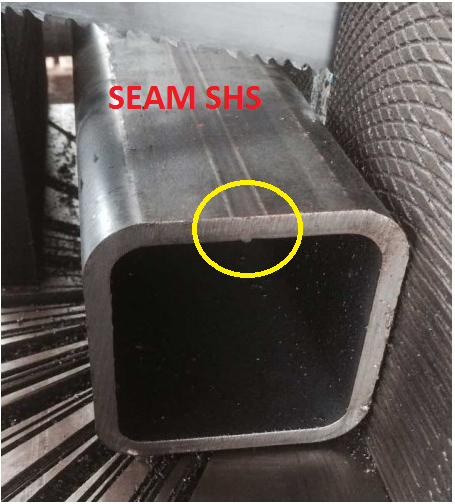
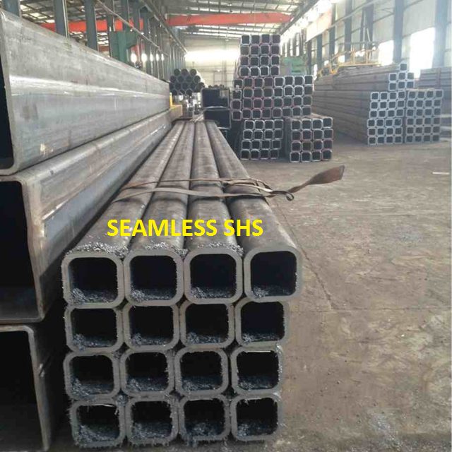
    In the market we are have two different types of profiles, One is Seam SHS and another one is Seamless SHS.

    See how there's a notch here? Ok now we need a bit more clearance. This is because of the process by which this member was created. It starts of like a flat piece of metal, and is basically folded into a square. So the notch will be on the inside, where it is difficult to smooth off.
    See how there’s a notch here? Ok now we need a bit more clearance. This is because of the process by which this member was created. It starts of like a flat piece of metal, and is basically folded into a square. So the notch will be on the inside, where it is difficult to smooth off.

    Notice there is no notch inside?
    Notice there is no notch inside? The clearance can be a little smaller in this case.

    If we use Seamless SHS profile, then we can erect the members, Otherwise if the SHS are of the seam profile type then we can’t erect the member – there is not enough of a clearance.

    Before carrying on the structural details we must discuss with Client/Fabricators and confirm which type of SHS they are going to use.

    If they have Seam SHS only, then we must reduce the stub profile and make more clearance for the easy erection.

    Written By Arokiaraj and his team; Our mistake in this regard was helpfully pointed out by Brett Kennard of Apollo Fabrication. Brilliant.


  • Create new layer filter

    This video explains how to create Layer property filters and layer Group filters for Autocad. nano cad should be same. My nanocad Lic is not yet installed. Using layer filters is a great help to manage your cad files.

    Using layers

    https://youtu.be/9pcJ7OYXUn8

    p

    roperly increases your productivity many folds

  • Setting dimensions style using a template cad file

    You can download the template cad file by clicking this link


    https://youtu.be/nFf-PHfCVKg

    late dim.dwg fileDIM . It is zipped file only because wordpress does not allow me to upload a .dwg file

  • T-Bars, Cut from UB, use fabricated or use ready made

    How to manufacture the T Bar is a question which frequently comes up.

    The various options are

    1. Make T-Bar from plates. (Involves welding plates together)
    2. Cut from UB. (Might include wastage)
    3. Buy Standard T-Bar. (May have its own constraints like minimum quantities)

    Up until now we were detailing T bars as fabricated using T Plates. But now one of our clients has given a catalog from GALINTEL. Click on this link to go to their website.

    Now whether a T bar should be option 1, 2 or 3 should a matter of preference of the fabricator irrespective of what is specified on the member schedule. Best course of actions is to RFI.