Architectural Drawing
- Concrete layout drawing
- describes the location and layout of the precast
- General arrangement drawing
- describes the building’s space arrangement, such as rooms, bathrooms, and so on.
- Window Plan and Elevations
- describes the size and location of the windows and doors.
- Arch elevation and its sectional elevations
- describes the architectural finishes and presentations on the exterior and interior.
- Stair plan & elevation drawings
- describes the details of the stairs, steps, and landing.
- Core wall plan and elevations
- describes the lift shaft drawings and their specifics.
Structural drawings
- Column schedules & details
- describes the column size and its reinforcement details.
- Core wall plan and elevation details
- describes the details of the lift/stair wall reinforcement.
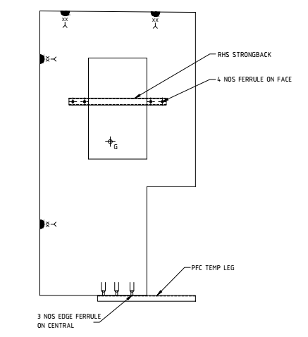
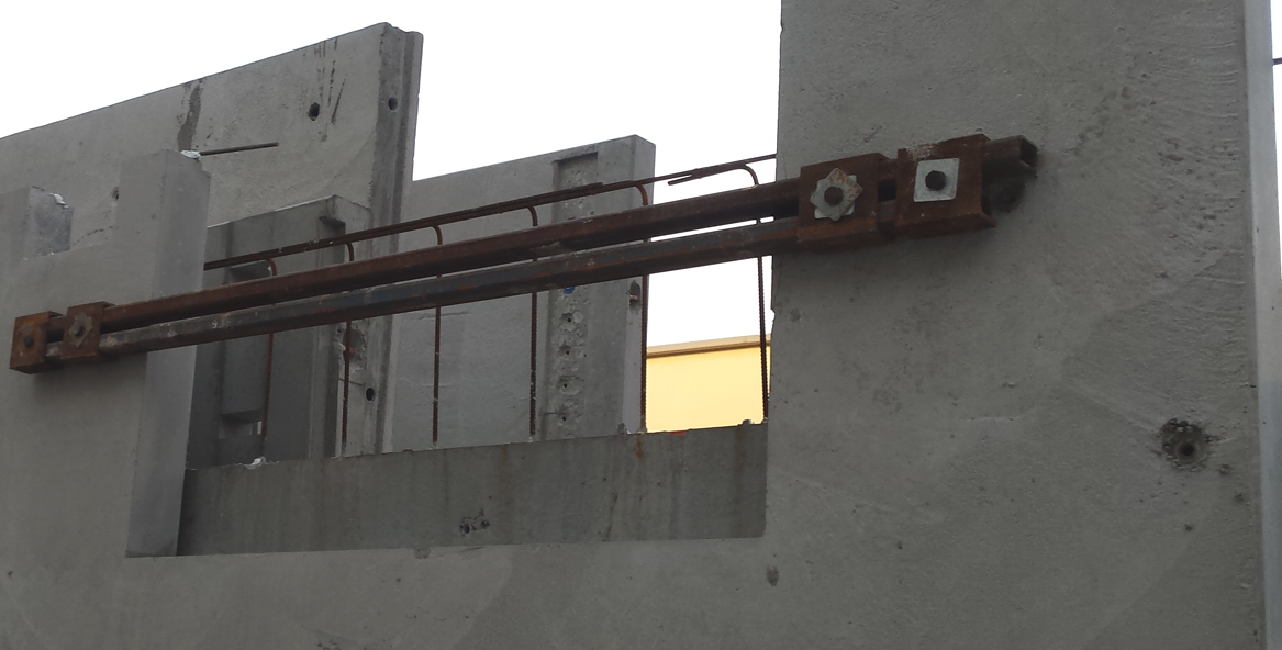
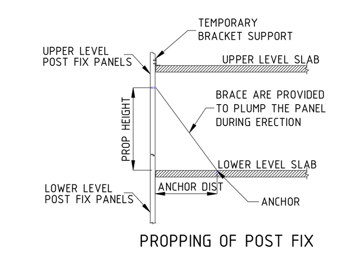
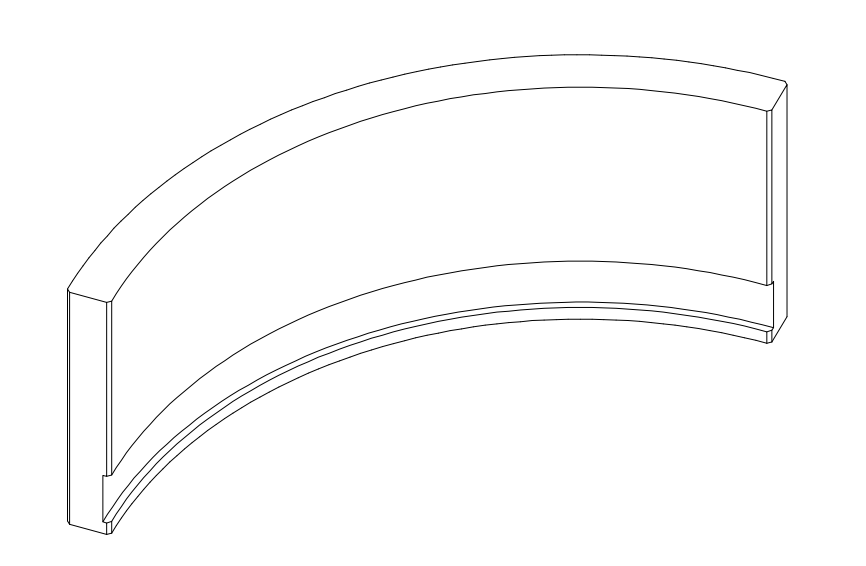
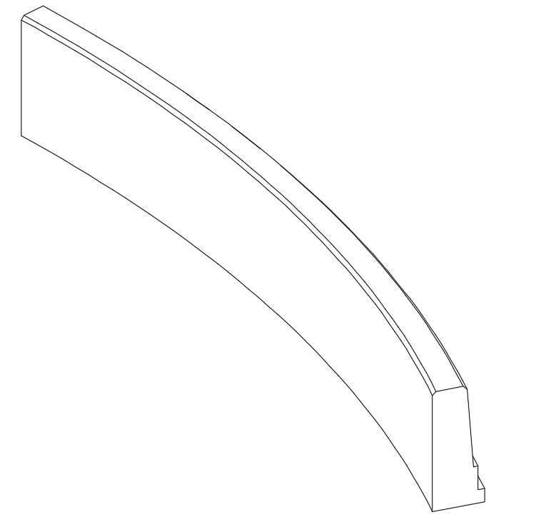
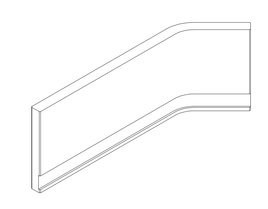
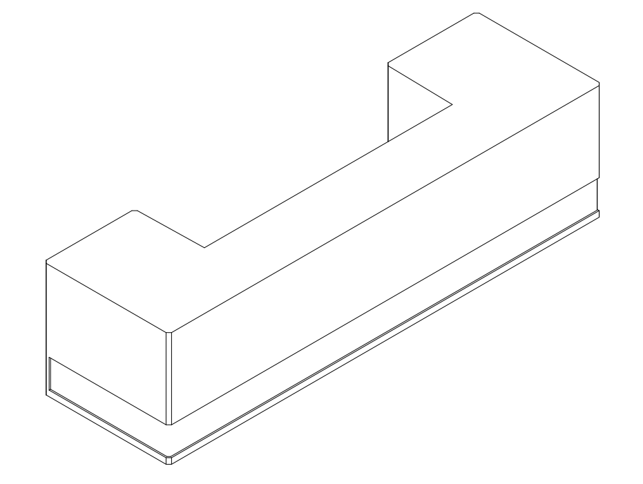
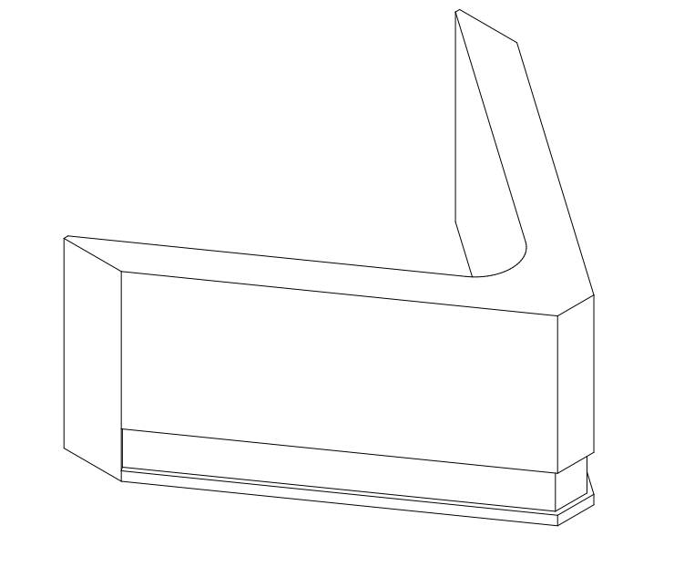
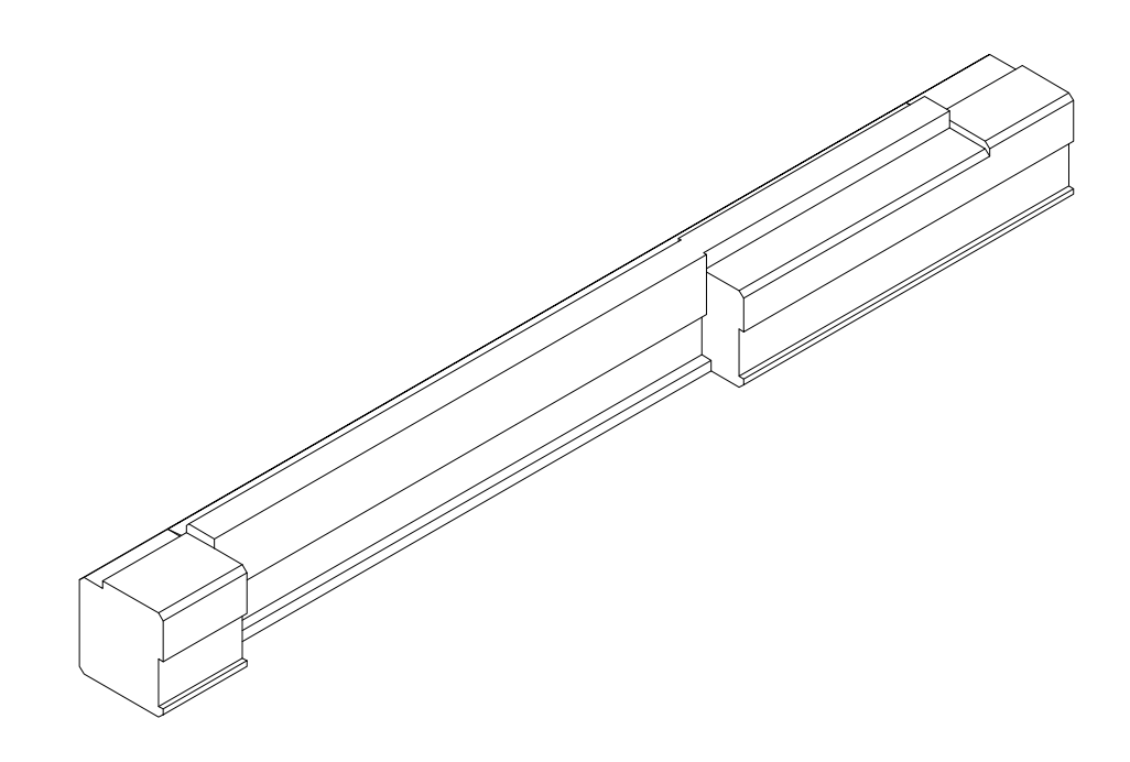
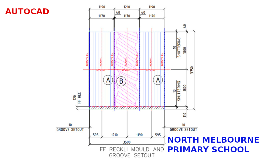
- Typical Precast Details
- describes the general reinforcement and its details.
- Typical stair details
- describes the stair landing slab and steps, as well as the reinforcing details.
- Slab profile plan and sectional details
- describes the thickness of the slab, the beam, and the reinforcement details (up and down).
- Ramp plan, section, and elevation details
- The Ramp Angle, Reinforcement, and Thick Sails are all described.
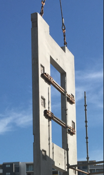
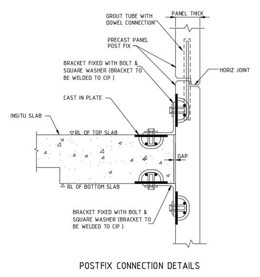
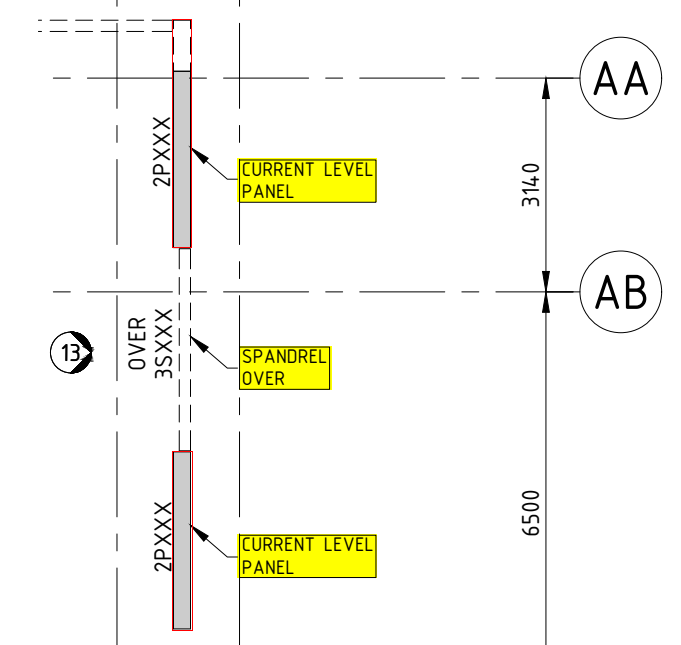
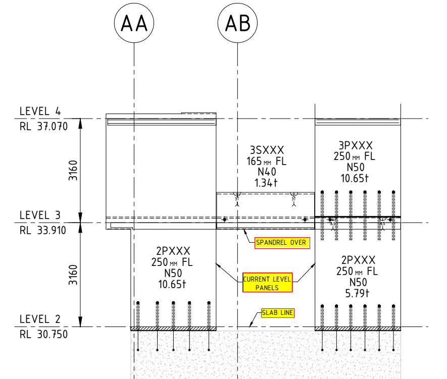
- Precast elevations & sectional details
- describes the reinforcement, grade of concrete, and additional reinforcement details.
Service drawings
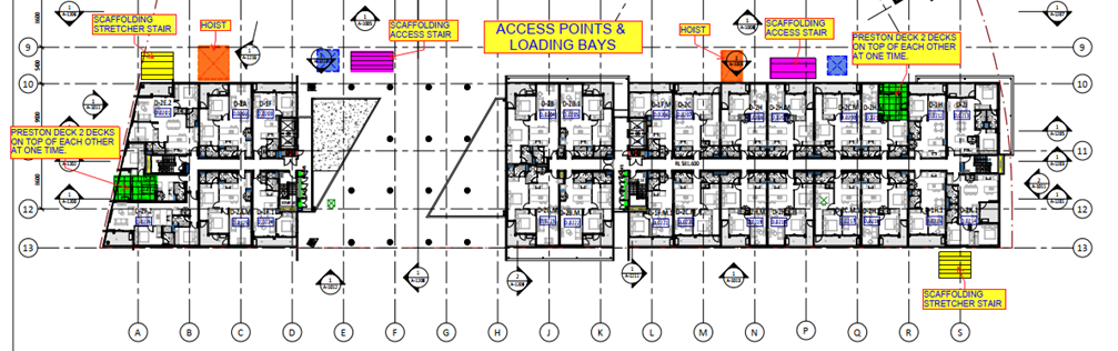
- Crane details
- describes the loading area and crane weights at various lifting points.
- Hydraulic drawings
- describes the drain or overflow opening and its details, among other things.
- Mechanical Penetration Details
- describes the AC duct opening, etc.
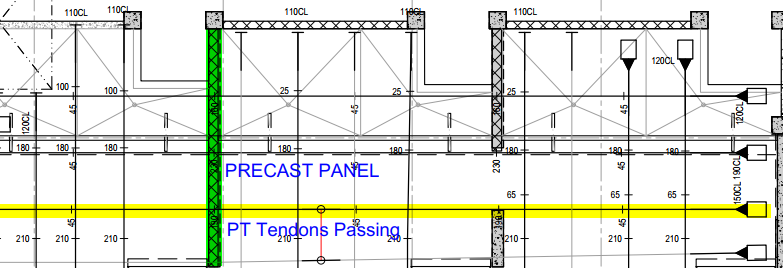
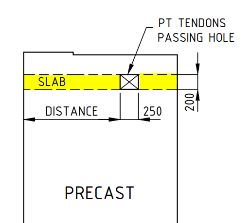
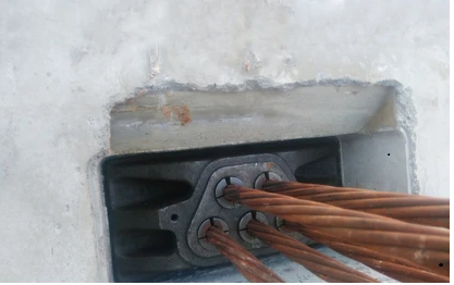
- Post-tensioning slab details
- describes the PT tendon passing areas and their specifics.
- Lift shaft drawing
- describes the lift shaft opening, the controller box, and its details.