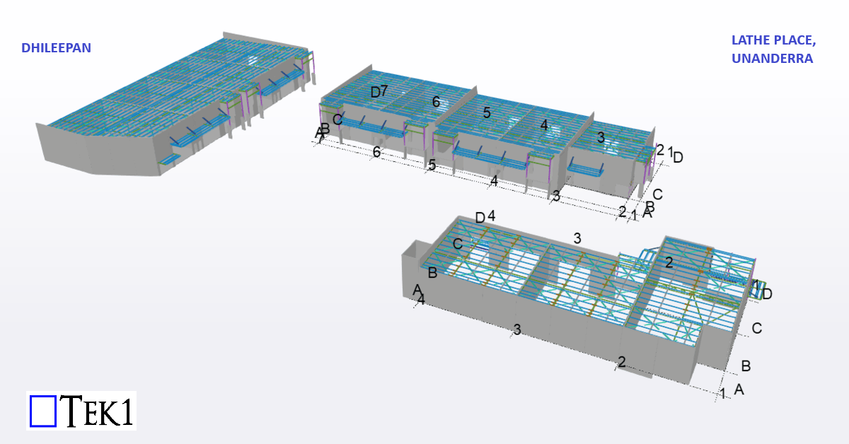
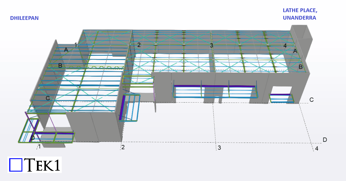
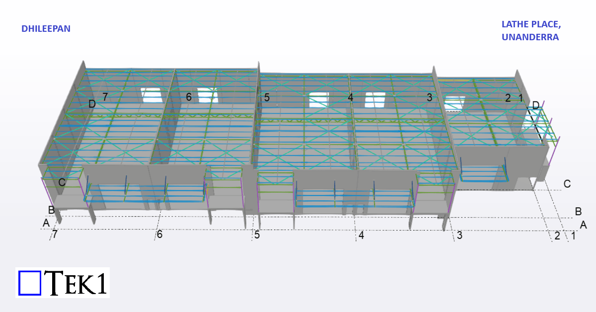
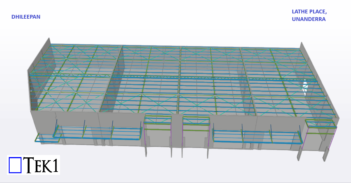
We are proud to be a part of the team in Mildura Christian College project.
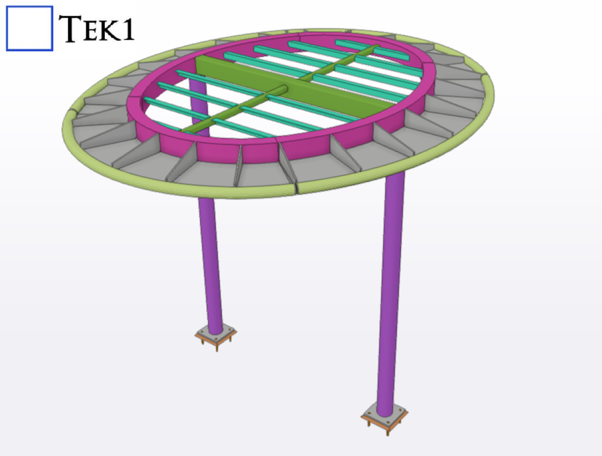
Our detailing team worked closely with architects to ensure tolerances and offsets were met without compromising design intent With a limited fabrication and erection window, our detailing team adopted a fast-track workflow using Tekla Structures for 3D modeling.
This allowed us to provide early shop drawings for procurement and parallel review of sections still under coordination.
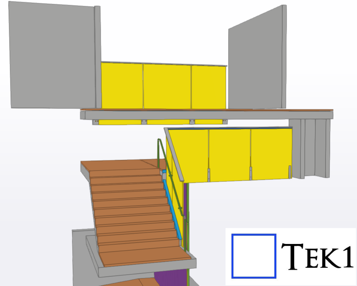
TEK1 completed a cladding project for a prominent organization in Australia. The goal was to provide claddings to buildings for aesthetic purposes. Apart from that, the client also wants us to detail handrails & glass balustrades for the stairs.
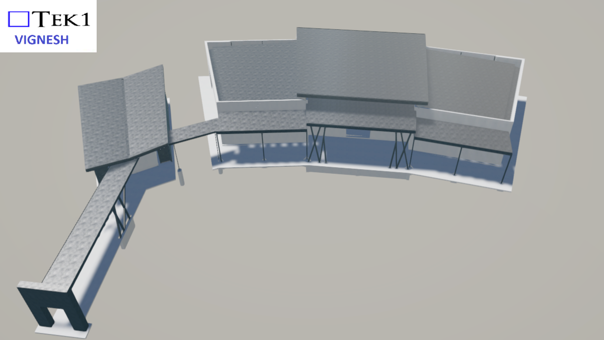
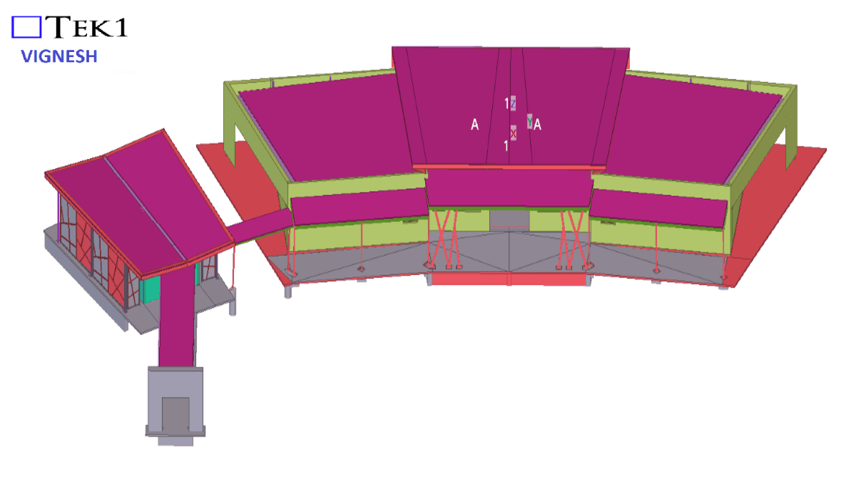
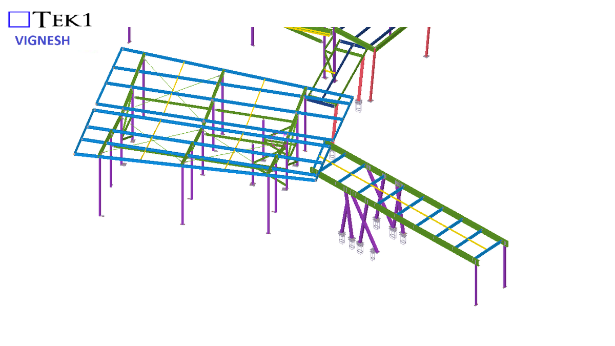
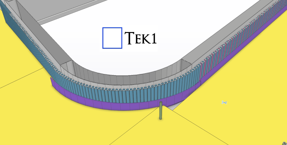
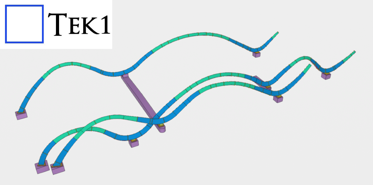
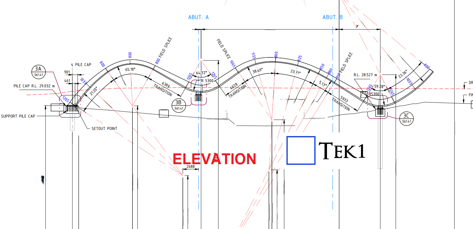
Recently, we were awarded a project to detail a curved section on the bridge for a reputed organization in Australia. The geometry involved presented some unique challenges.
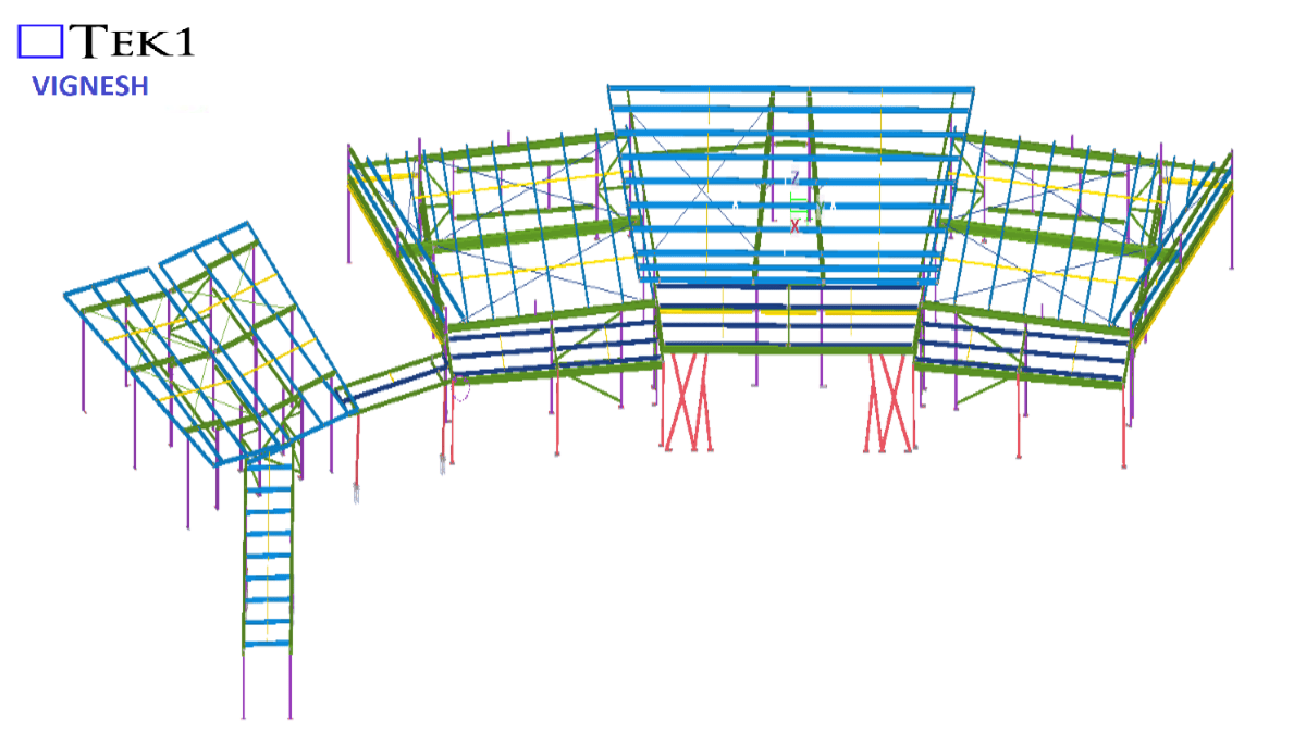
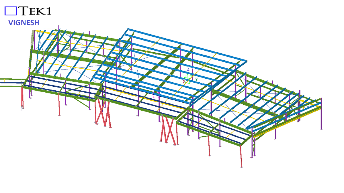
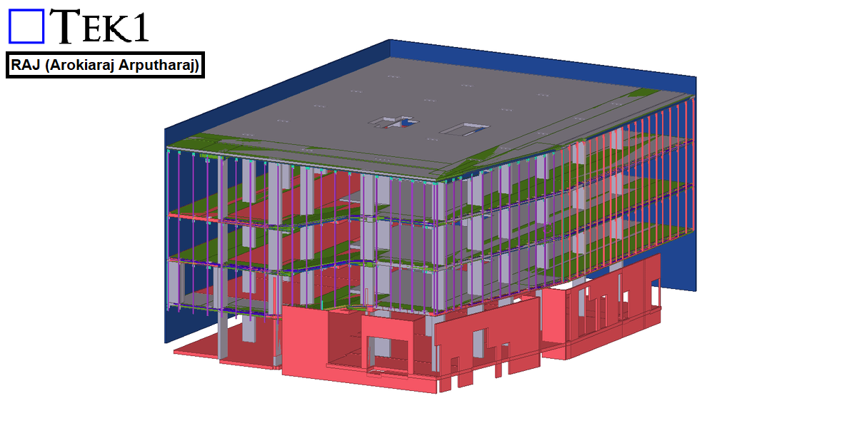
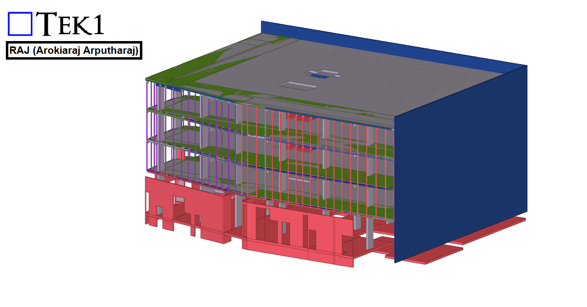
From the elevation, the structure followed a non-linear zig-zag curvature, creating a dynamic and aesthetically driven form.
In this blog, we share a proposal we made to the builder to make installation easier on-site.
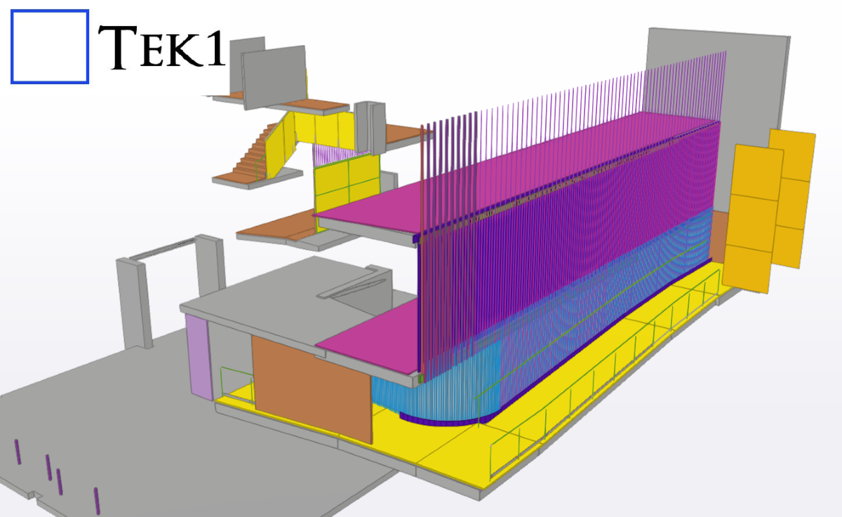
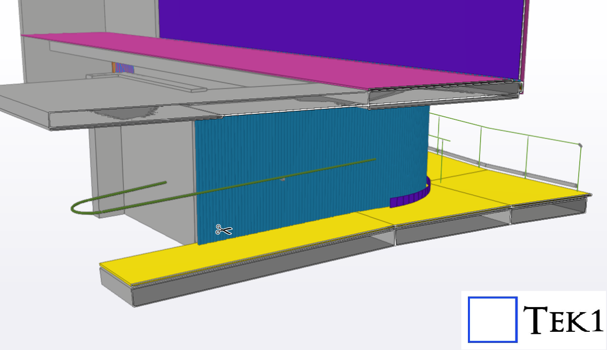
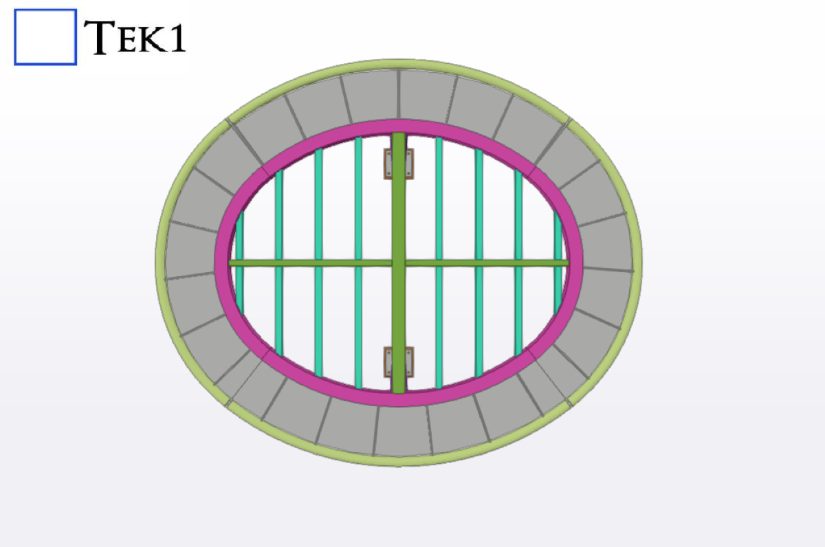
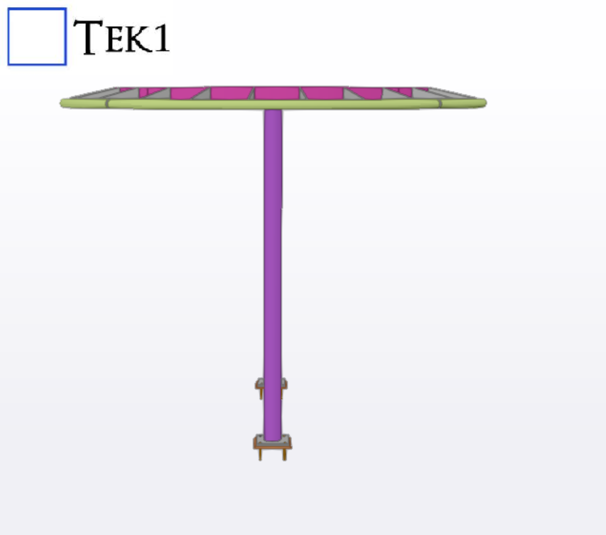
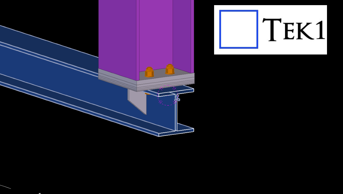
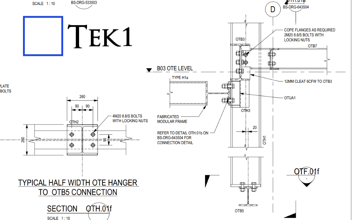
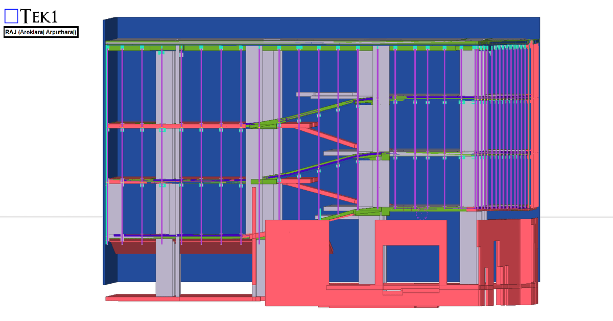
In the OTE platform steel, we provided a PSD beam (OTB5) to support the platform screen doors below. These beams will later need to coordinate with the door manufacturer’s system.
However, in practice, structural steel is rarely placed in the exact designed level due to factors like concrete alignment, mill tolerances, and site conditions. If the beam is installed as per the design without adjustment options, it may not match the required level for the doors.
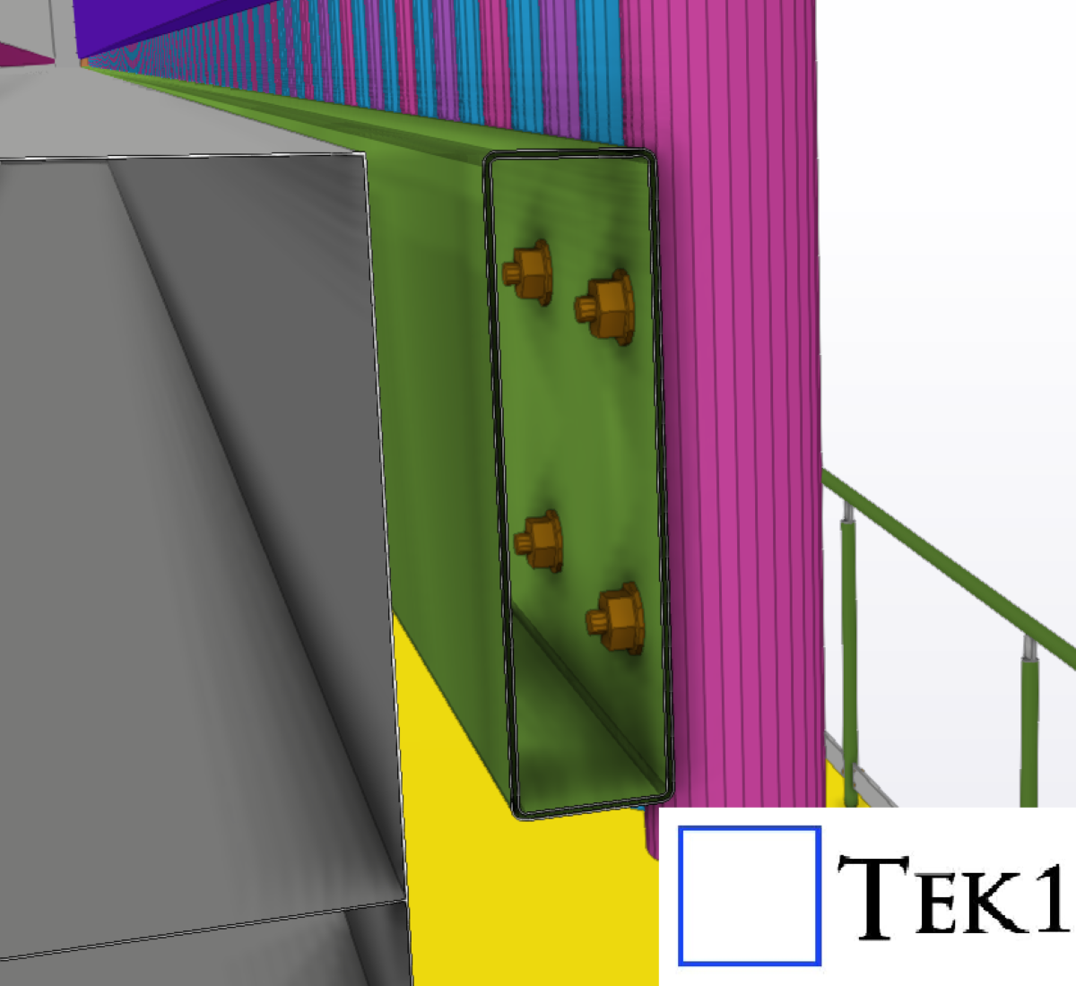
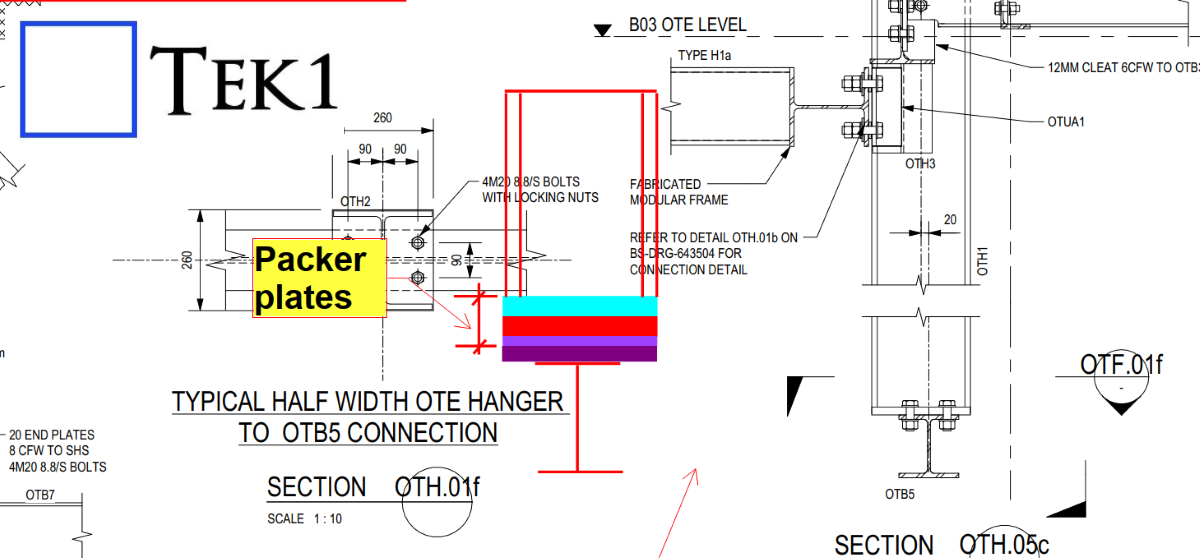
To solve this, we proposed adding packer plates so the PSD beam level can be adjusted during installation.
The client accepted our proposal, and this solution will make the erection and alignment process much easier on site.
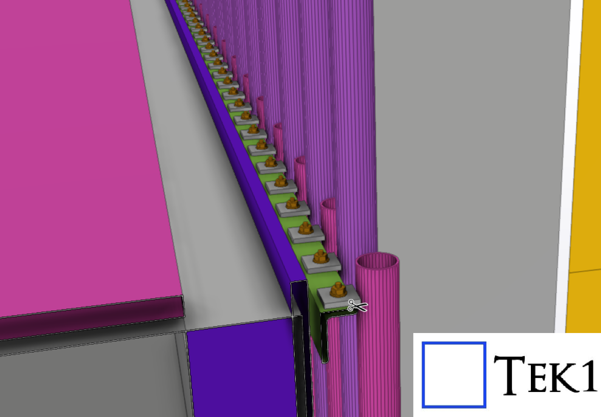
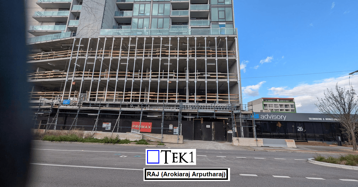
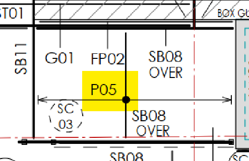
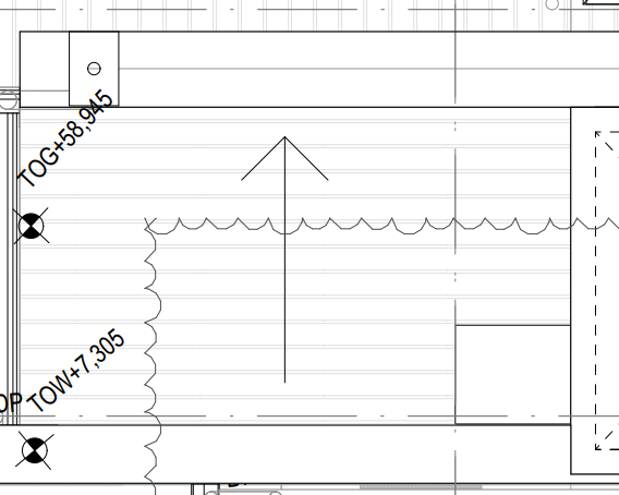
For the 27 Scott Street project, the client requested that the façade posts be installed with sufficient clearance so that the fixing anchors do not clash with the PT cable lines.
We carefully followed the client’s requirements and coordinated the design to ensure that the anchors clear the PT cable lines. The steel was successfully erected without any issues.
We would like to thank the client for giving us the opportunity to be part of this project.
In Australian steel detailing, understanding roof and purlin specifications is essential for delivering precise and efficient designs. In this blog, I’ll share an experience highlighting the significance of addressing roof slope issues during detailing.
The Issue
In a structural drawing, the purlins were shown running north-south, which suggested that the roof slope would be east-west (since purlins are always perpendicular to the roof slope). However, when we reviewed the architectural drawings, the roof slope was indicated as running north-south—a direct contradiction.
The Resolution
We raised the issue with the client, who confirmed that the architectural drawings superseded the structural ones. Following this clarification, updated drawings were issued, with the roof slope correctly aligned in the east-west direction.
Key Takeaways
Cross-Check Drawings: Always verify alignment between structural and architectural drawings, especially for critical elements like roof slopes.
Communicate Early: Raising discrepancies early saves time and prevents costly rework.
Stay Updated: Ensure you work with the most recent drawings to avoid confusion.
Roof and purlin alignment might seem straightforward, but even small errors can have significant implications. Attention to detail and proactive communication are key to successful detailing.