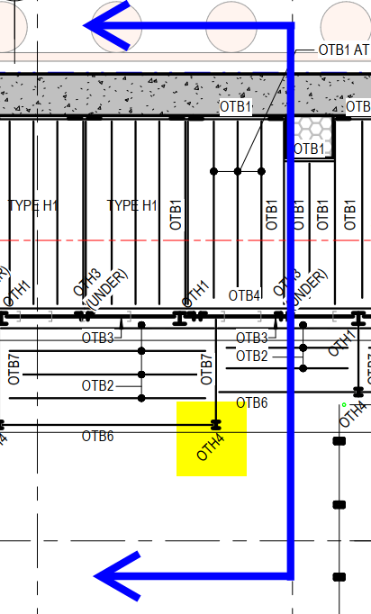
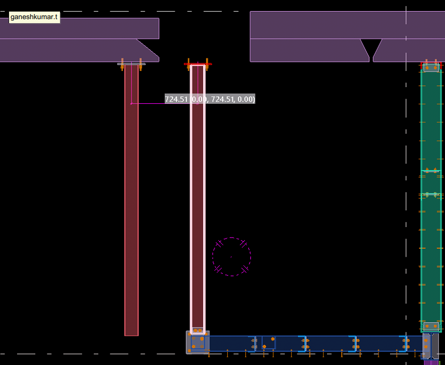
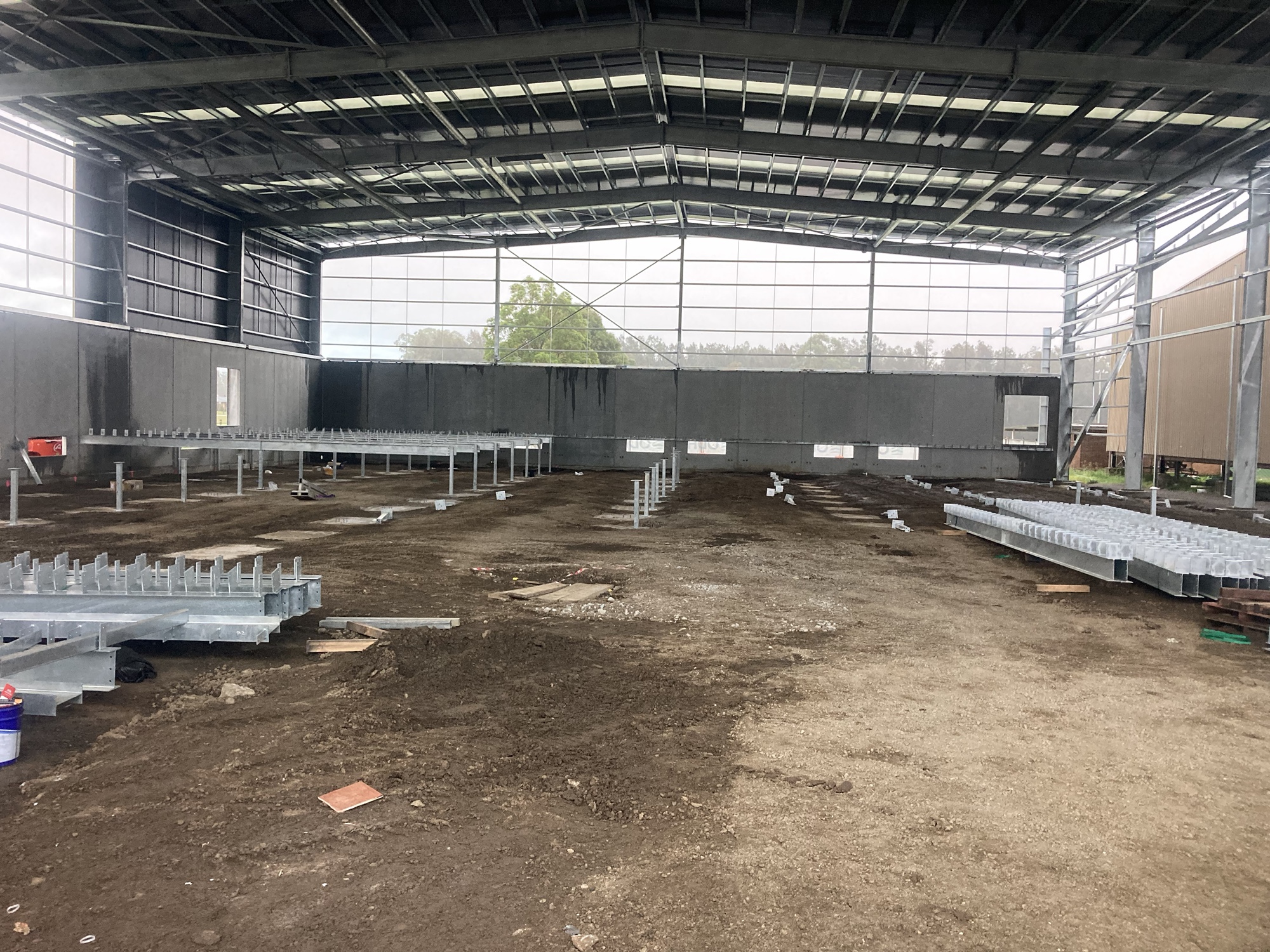
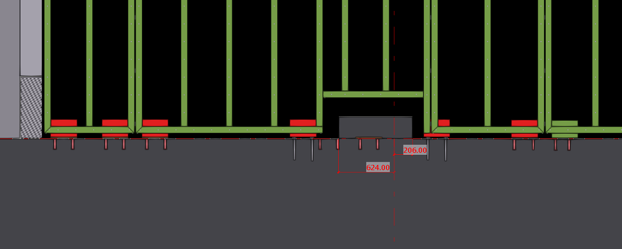
In this blog, I’d like to share an issue we faced related to hanger locations.
In this job, the floor steel was supported from the slab soffit. Initially, we placed the hangers as per the design drawings. However, during coordination with the concrete model, we discovered a slab void exactly at one of the hanger locations — meaning there was no concrete support available for that hanger.
Fortunately, we identified the issue before fabrication and raised it with the respective manager for correction.
When detailing steel, especially hangers or supports connected to concrete, it’s crucial to check the concrete model. Focusing only on the steel scope can lead to such clashes. Always verify slab and concrete details at the steel connection points to avoid costly rework later.
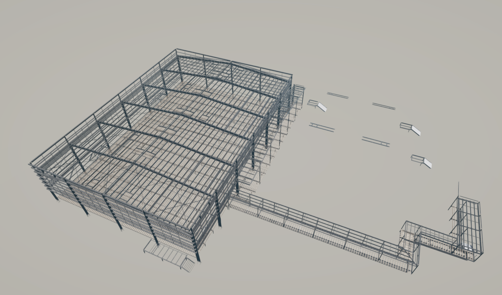
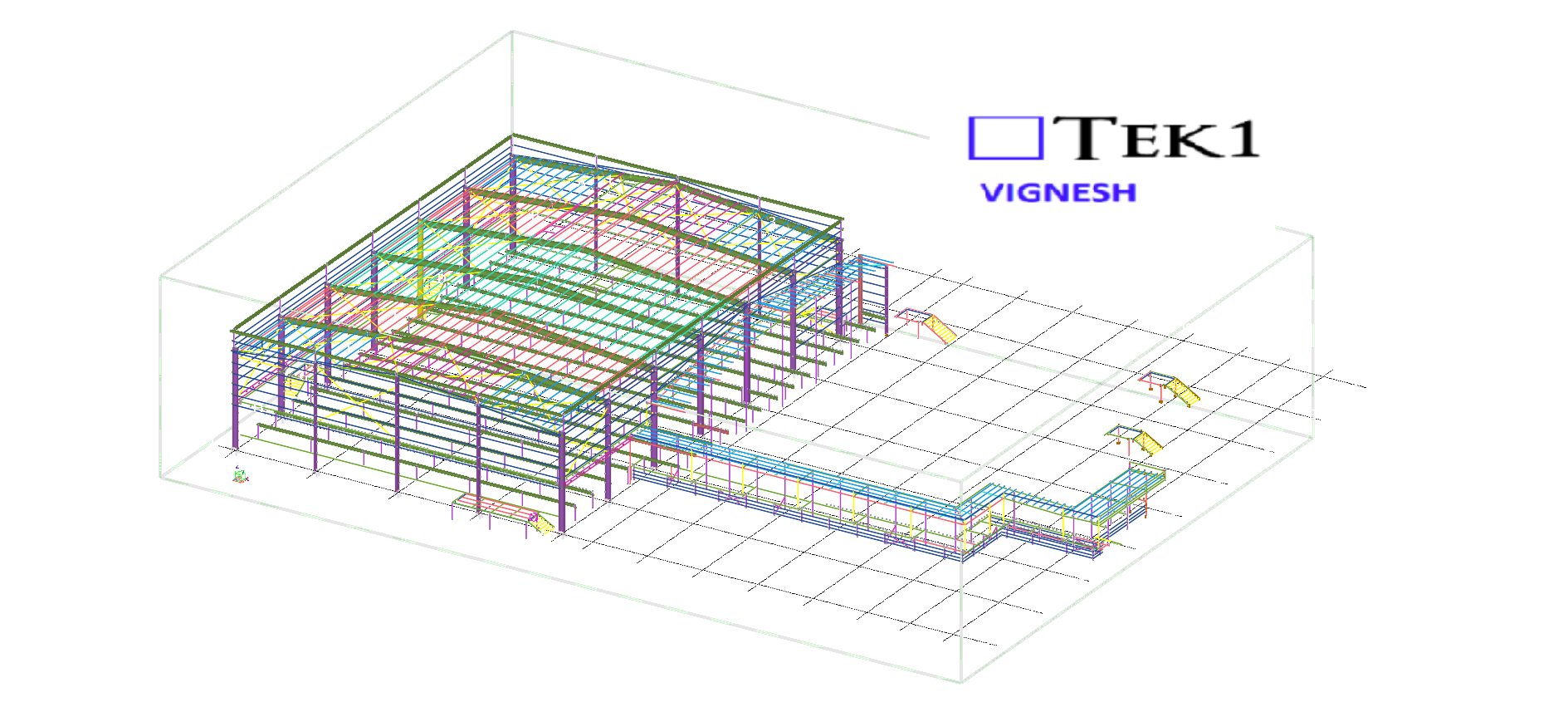
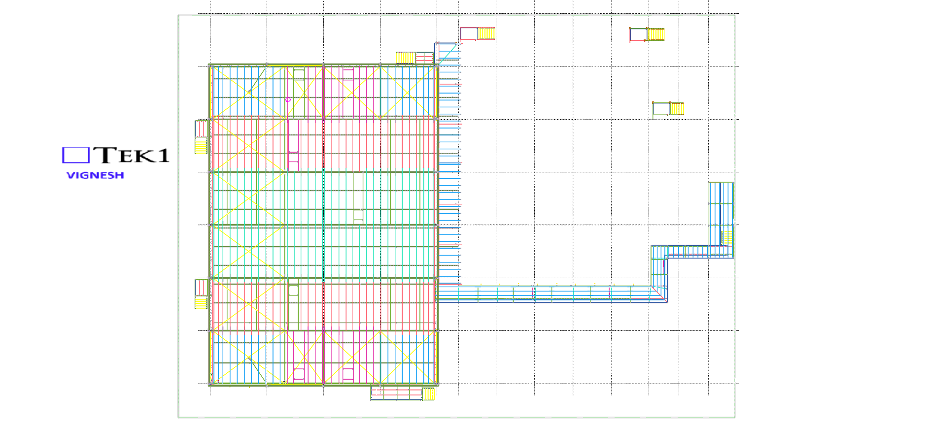
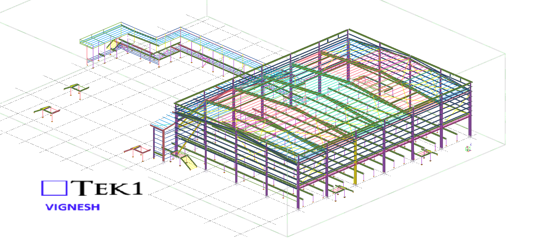
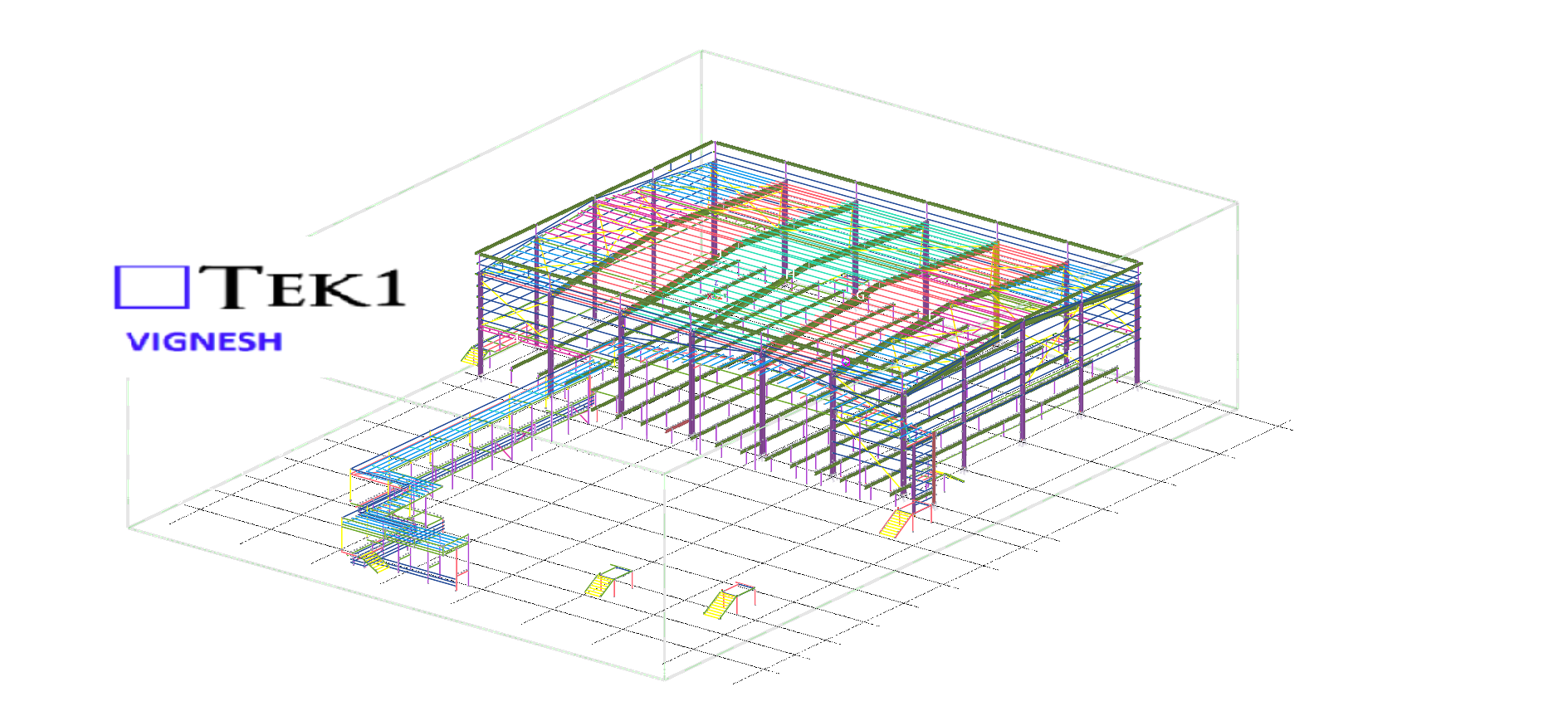
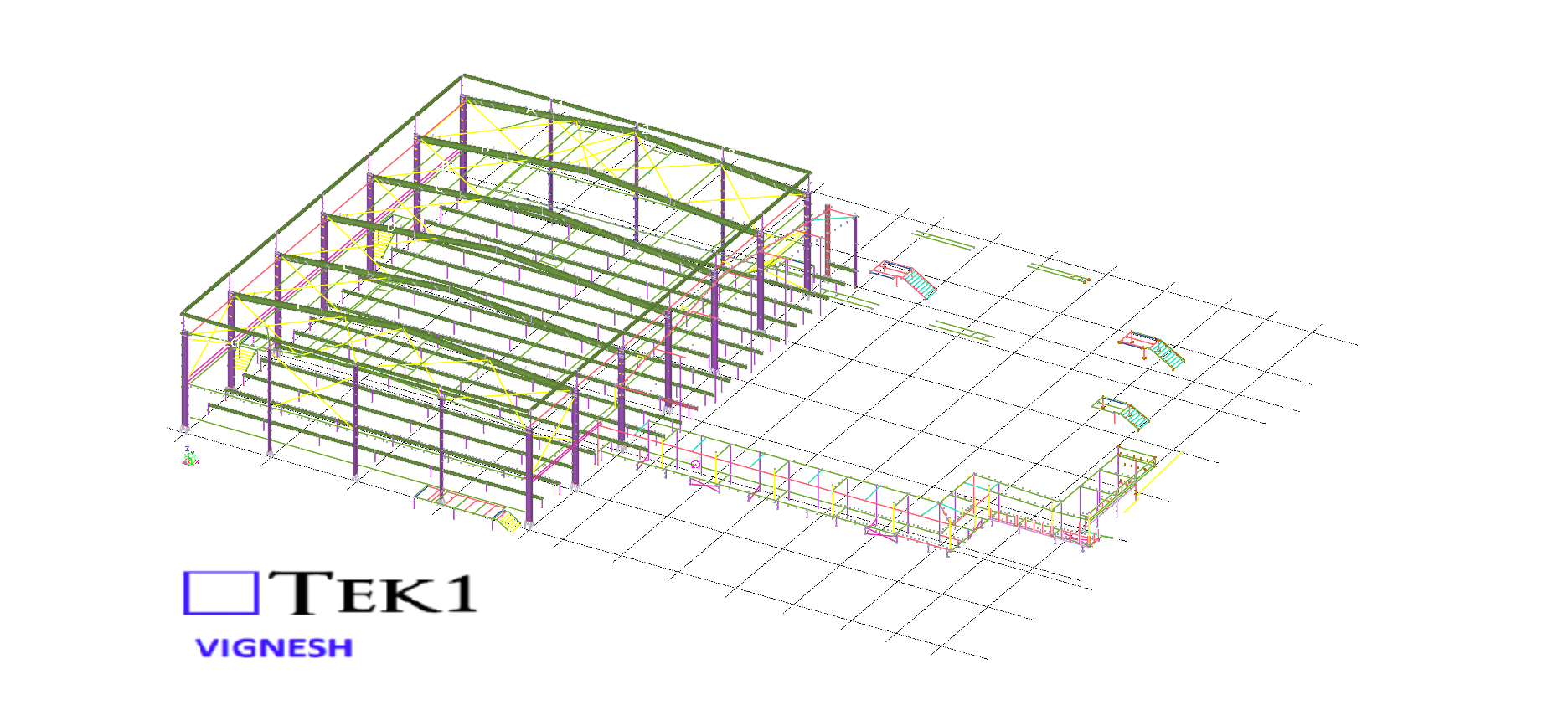
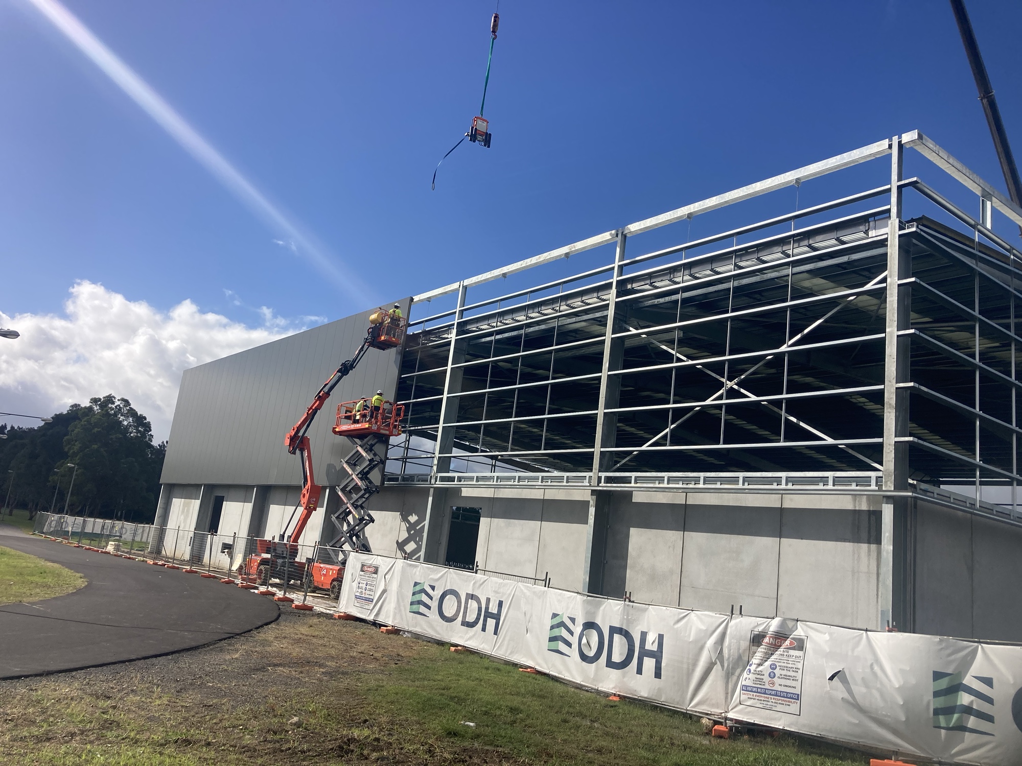
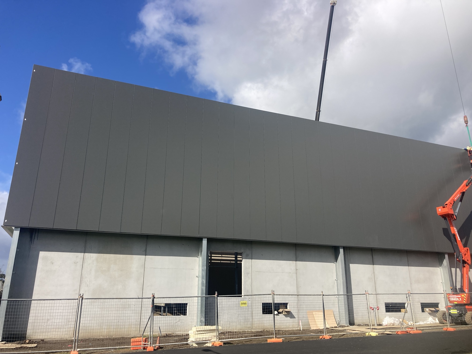
Our detailing team worked closely with architects to ensure tolerances and offsets were met without compromising design intent With a limited fabrication and erection window, our detailing team adopted a fast-track workflow using Tekla Structures for 3D modeling.
We are proud to be a part of the team in IRON_ARENA_SPORTS_CENTER project.
This allowed us to provide early shop drawings for procurement and parallel review of sections still under coordination.
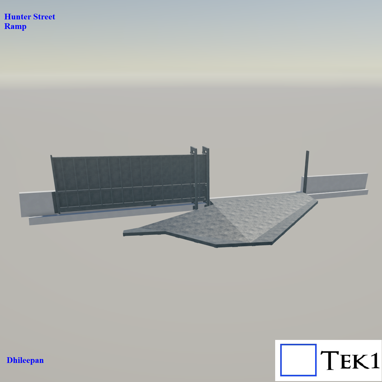
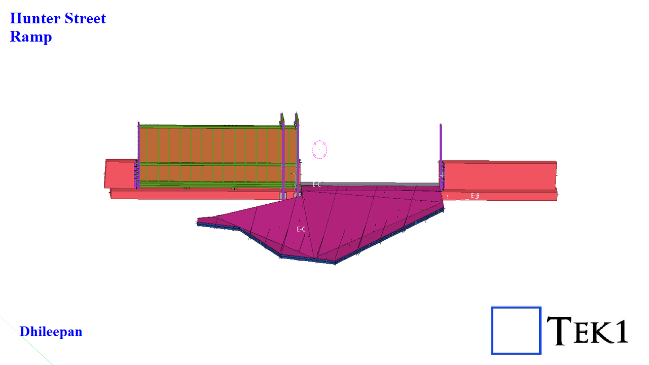
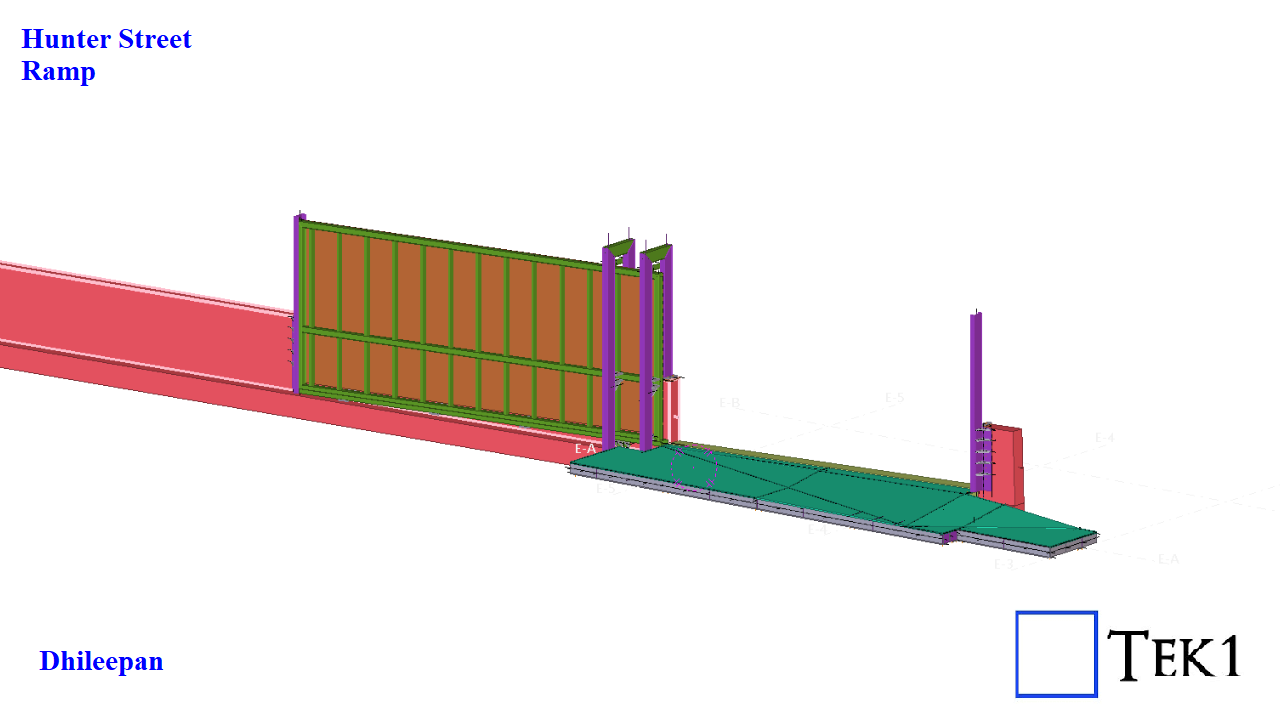
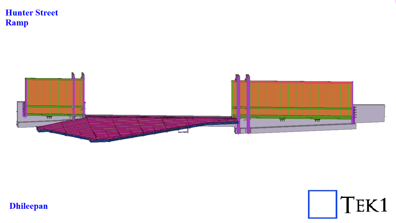
The Hunter Street Project involves a total of three unique ramp and gate assemblies, each designed with a distinctive geometry and function.
Unlike conventional ramps that slope in a single direction or follow a straight alignment, these ramps are far from ordinary. Each one features multiple slopes and apex lines, requiring precise modeling and coordination to achieve seamless transitions and accurate fitment on site.
The associated gate systems include both single-leaf and double-leaf sliding gates, each integrated carefully with the ramp slopes to ensure smooth operation and proper clearances.
Structurally, each ramp is composed of a series of 4 to 8 frames. Every frame includes:
A chequer plate deck at the top for slip resistance and durability.
A base plate at the bottom for connection and stability.
Waffle-type stiffeners sandwiched between, providing rigidity while minimizing weight.
This setup requires engineering precision and modeling expertise. Tek1 had to provide inputs and suggestions to design the slopes in a way that ensures smooth operation of the sliding gates without imbalance.
We hope you found our previous blogs on the Sydney Metro project insightful. If you missed them, check them out.
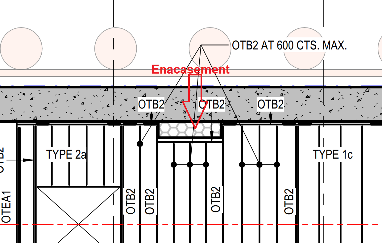
In this blog, I’d like to share an important lesson about concrete encasement for conduits that every steel detailer should keep in mind.Normally, conduit encasement falls under electrical scope, so detailers don’t focus much on it. However, the encasement’s location and size can directly affect the steel layout — as we discovered in one of our projects.
We detailed the steel as per design drawings, but on-site, the encasement dimensions varied. Some conduits were larger, others smaller, which caused clashes between the steel and the encasement, and in some areas, created unwanted gaps. This required on-site modifications to our steel.
When detailing steel near conduit encasements, always verify the actual encasement size and location before releasing fabrication drawings. Small checks early in the process can prevent major issues and rework on-site.
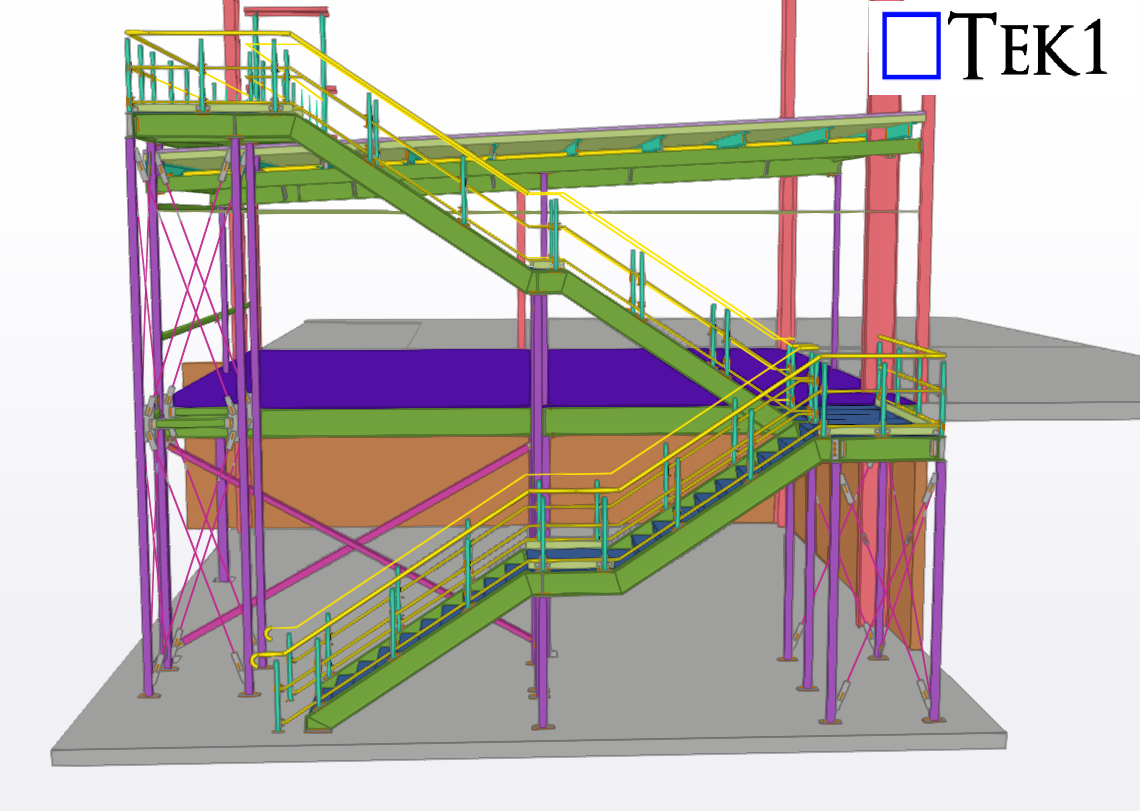
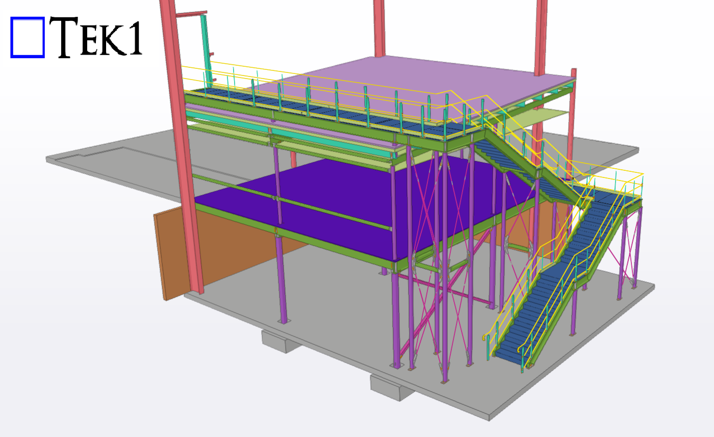
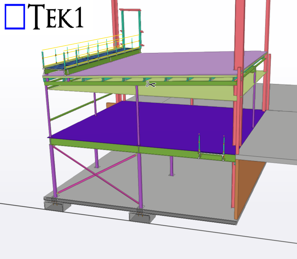
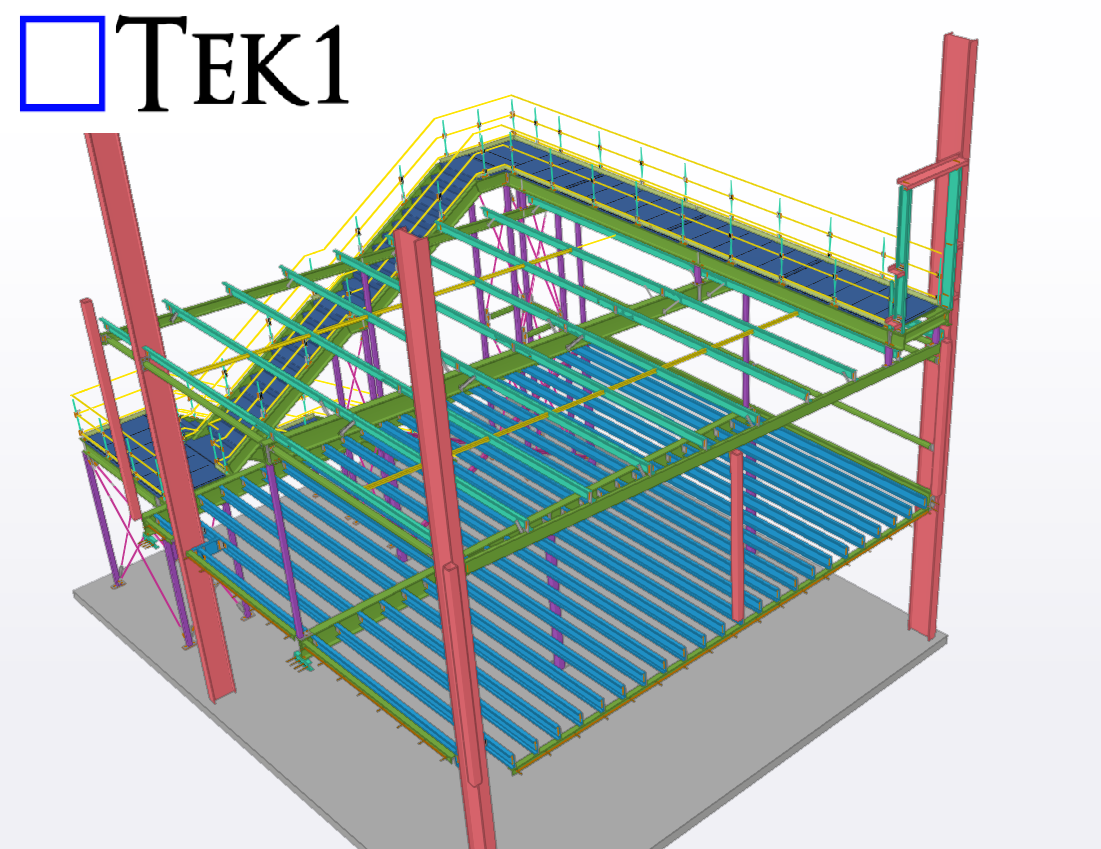
TEK1 recently completed a Mezzanine steel & stair for a prominent organization in Australia. The goal was to provide detailed support steelwork for mezzanine floor & stair including handrails.
While detailing a project for a leading organization in Australia, the client asked us to calculate material quantities for production and procurement.
However, this involves high risk.As detailers, we don’t control the nesting process — which depends on factors like sheet size, scrap management, and fabrication methods. Each fabricator uses different nesting techniques. If we provide material calculations without knowing their exact process, the numbers could be inaccurate.Any miscalculation could lead to over- or under-procurement, and the blame may fall on the detailer.
Even if the client is willing to pay for it, detailers should avoid taking on such high-risk tasks. Stick to your scope and let the fabricator handle material estimation based on their own nesting and production methods.
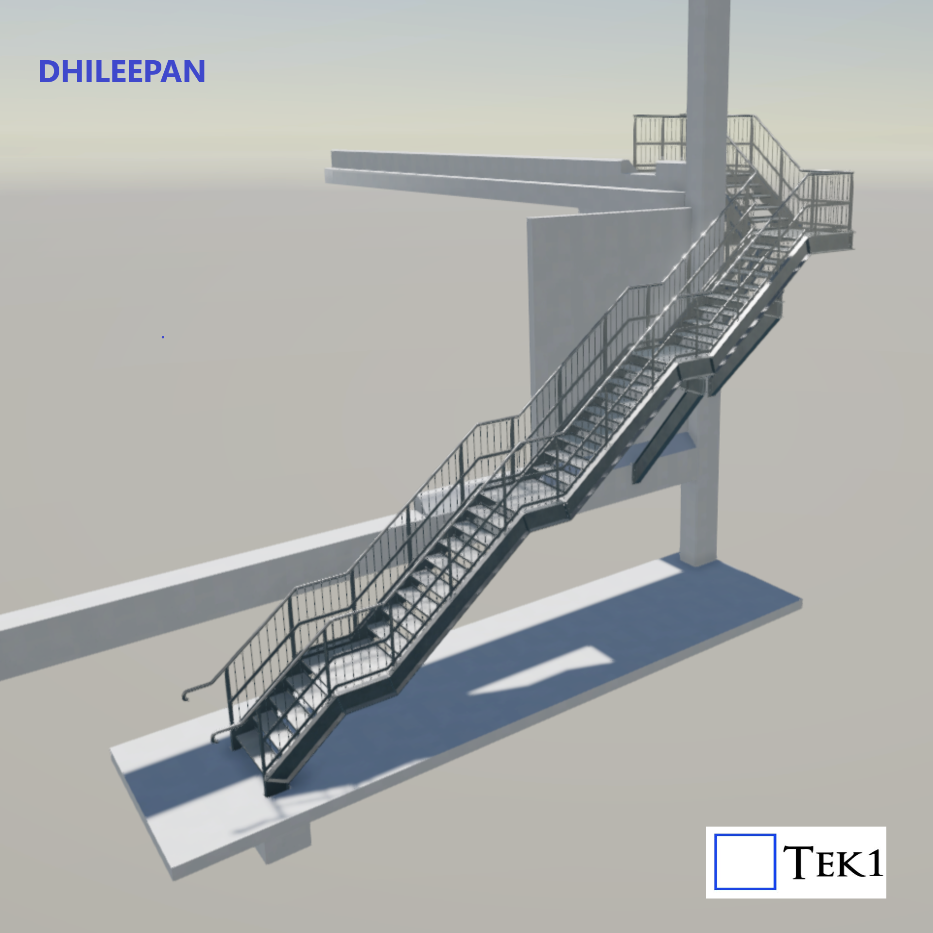
Recently, we received a stair project that had already been detailed by another party and even approved by the design consultants. For reasons unknown, the project eventually came to Tek1.
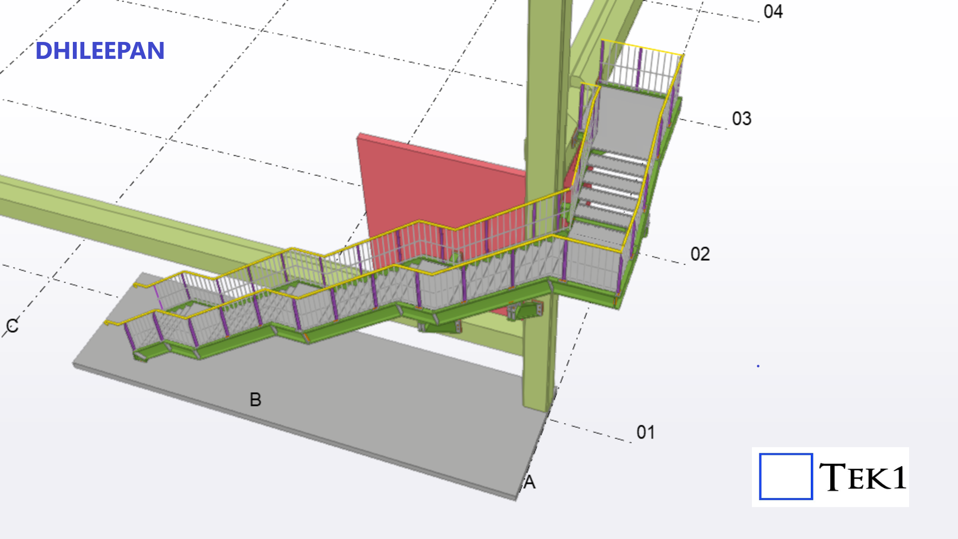
The scope involved a large five-flight stair with a 90° turn. We were provided with the GA drawings and assemblies prepared by the previous detailer, stamped with approvals, and instructed to simply follow the approved drawings for any RFIs raised.
At first glance, it would have been easy to assume everything was in order. But at Tek1, we believe that blindly following drawings — even “approved” ones — is risky. Every project deserves a careful check against standards.
The Error That Changed Everything
During our review, we noticed a critical issue: while all risers were at 190 mm, one riser was set at just 149 mm. This not only broke the uniformity but also violated the applicable stair standards.
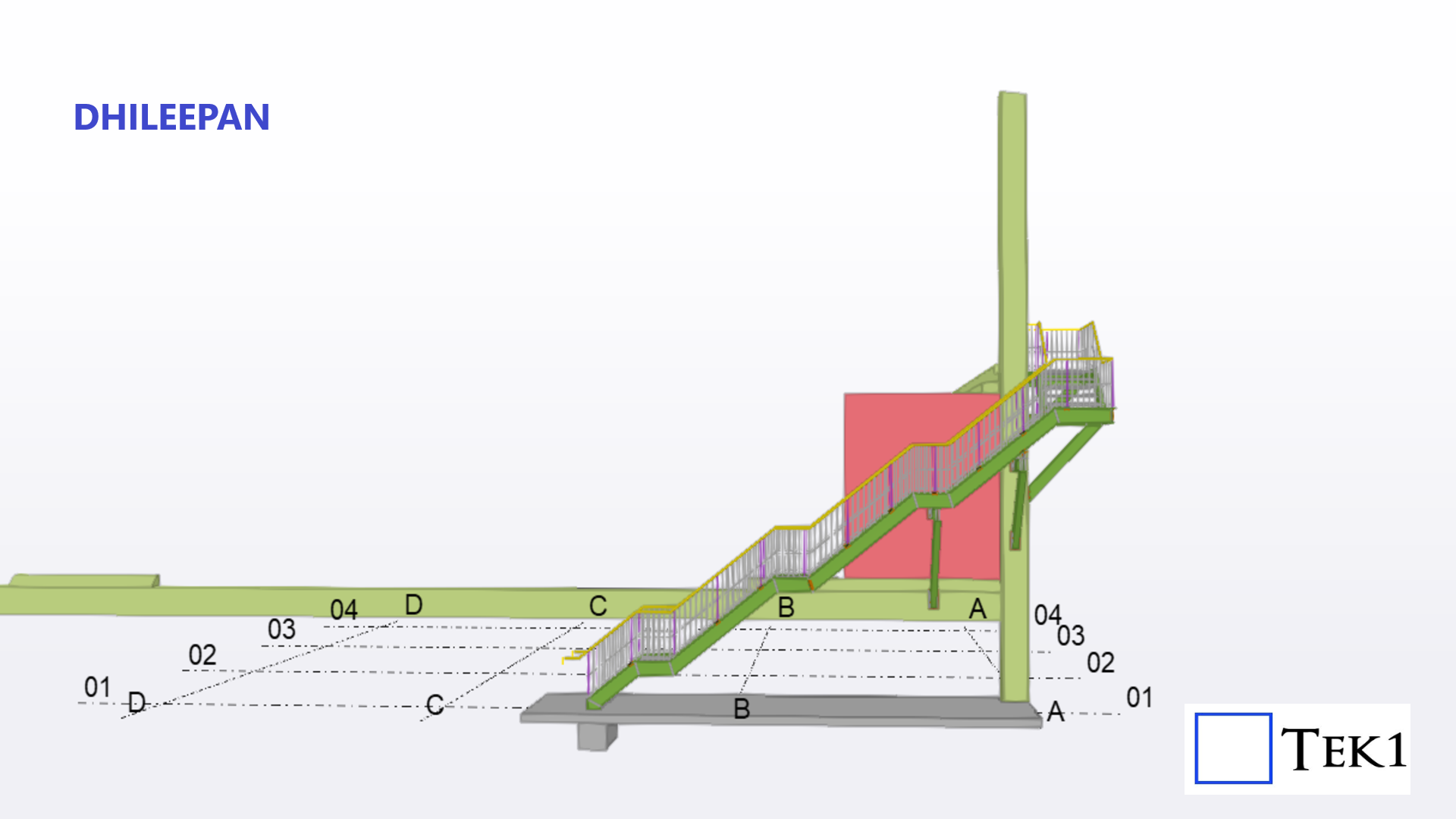
We immediately highlighted this to the client. What seemed like a “small” mismatch in a single tread had major implications. To correct it, the entire stair had to be revised:
Riser height was adjusted to 188 mm.
All mid-landing RLs shifted.
Stringer slopes changed.
Handrails and support frames were reworked.
In short, one overlooked error had a ripple effect on the entire structure.
Lessons Learned
Projects that land with us after being dropped by other detailers often arrive with extreme urgency, as valuable time has already been lost. But no matter how hectic the schedule, Tek1 follows one principle: check the input drawings against standards before proceeding.
This extra step not only avoids costly errors but also ensures safety and compliance — something no deadline should compromise.