TEK1 recently completed a media wall support project for a prominent organization in Australia. The goal was to provide detailed support steelwork for a large media wall screen — with a unique challenge.
Unlike most projects, we didn’t receive any structural design drawings. Instead, we were given only a concept design, leaving it to TEK1 to determine suitable steel profiles and connection details.
Our team carefully studied the concept and nominated appropriate profiles for each connection based on feasibility, strength, and ease of fabrication. Once the detailing was complete, we submitted it to the structural engineer for review.
The engineer approved our detailing with minimal changes, which helped speed up the process and made things easier for the client. The use of different profile types also optimized the design for practicality and efficiency.
We are proud to be a part of the team in VSBA School-51 project.
Our detailing team worked closely with architects to ensure tolerances and offsets were met without compromising design intent With a limited fabrication and erection window, our detailing team adopted a fast-track workflow using Tekla Structures for 3D modeling.
This allowed us to provide early shop drawings for procurement and parallel review of sections still under coordination.
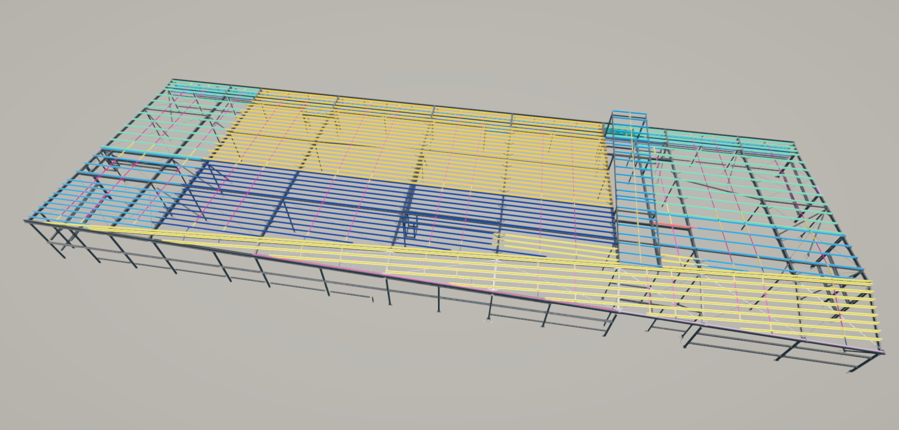
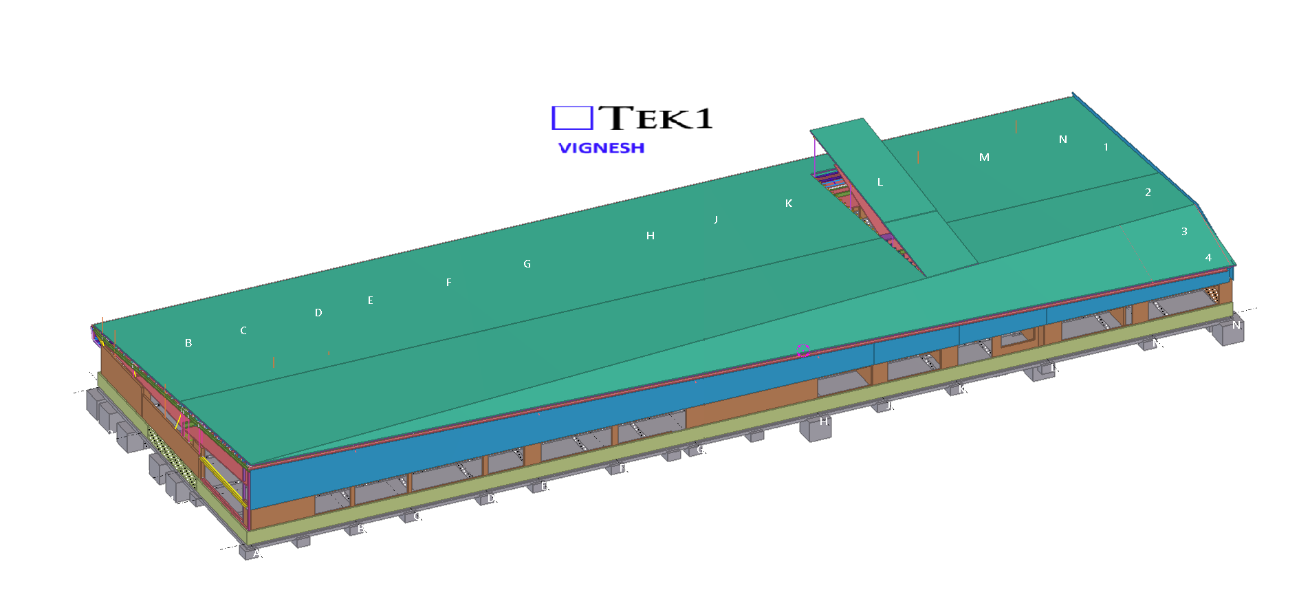
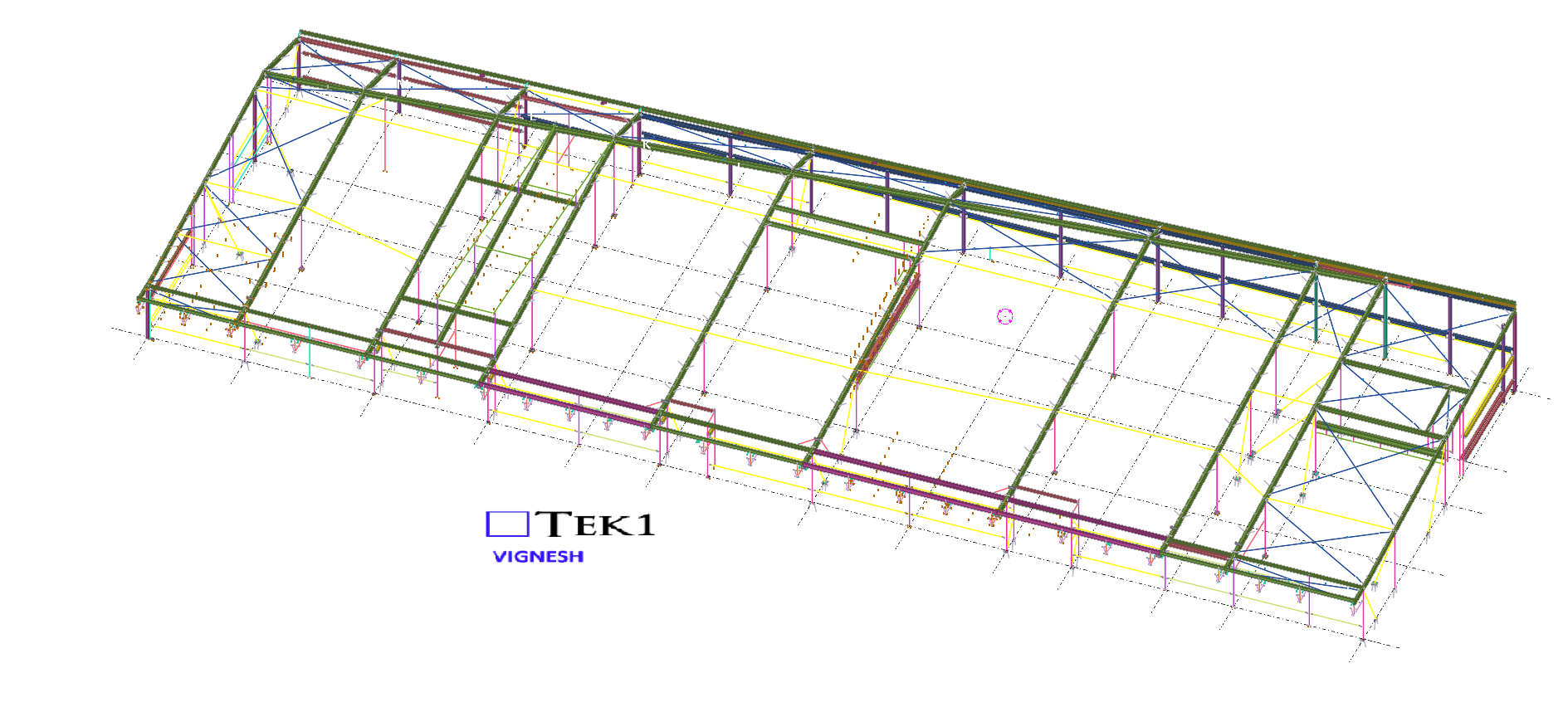
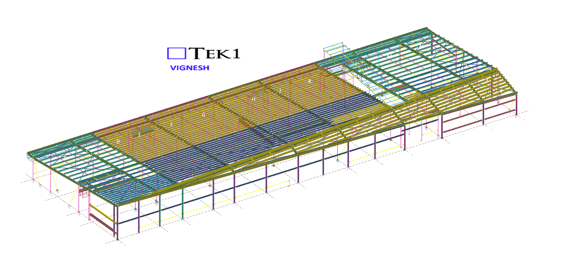
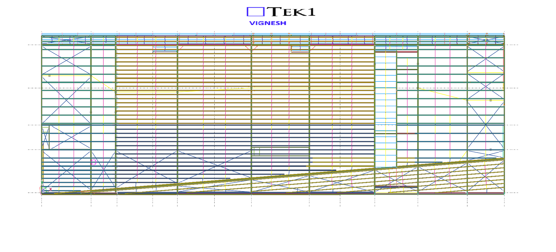
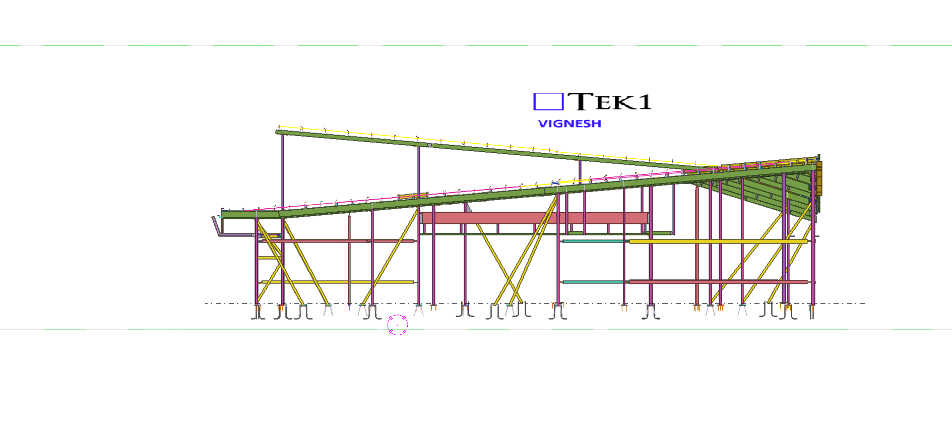
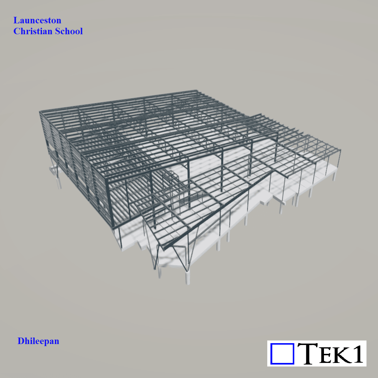
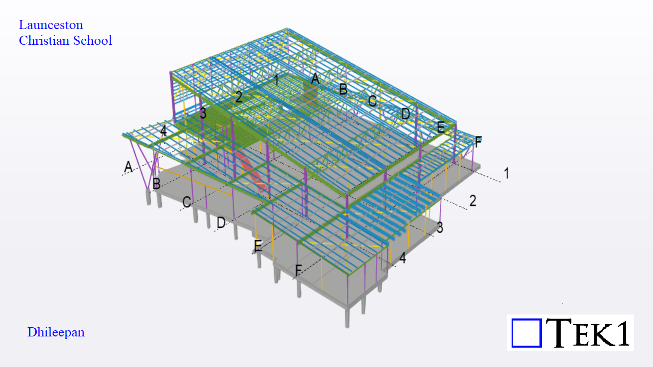
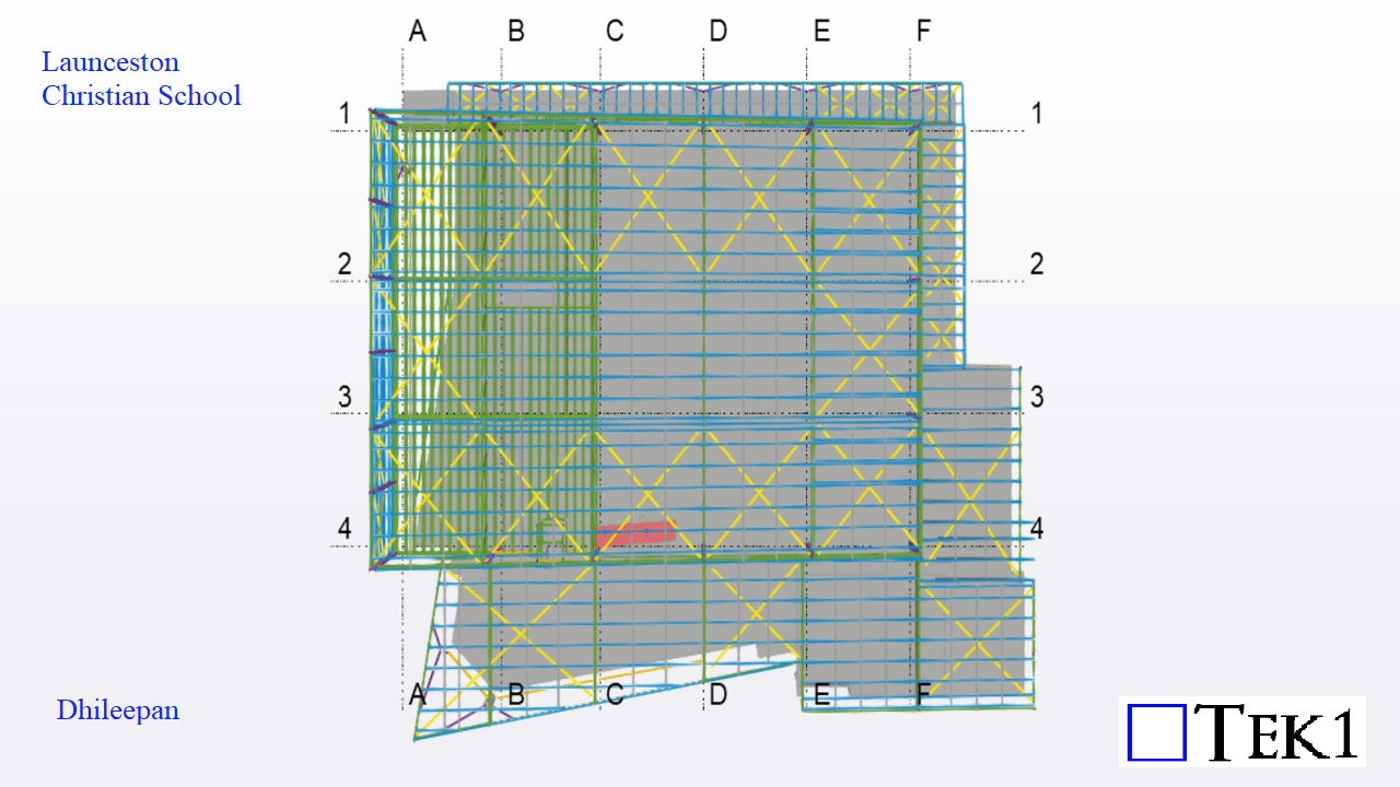
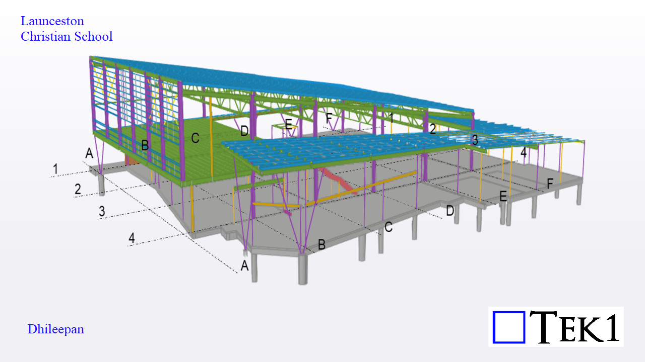
Let’s dive into the exciting expansion at Launceston Christian School in Tasmania—a thoughtfully designed new building covering an area of 1,440 square meters. This structure adds essential facilities to the campus, including classrooms, an auditorium, a storage room, and a library.
Challenges:
A key engineering challenge in this project was related to the cast-in base plates. These base plates had to be finalized and fabricated before the slab pour could begin. This required us to release accurate base plate fabrication drawings and exact location details early in the project timeline.
Since altering column positions later would not be feasible—especially if rafter alignments or other components demanded changes—we had to finalize all column locations at the earliest stage. This meant that the column modeling had to be both precise and quick.
Once the column layout was locked in, the modeling of the beams and girts progressed smoothly without any complications.
This project serves as a great example of how early coordination, clarity in design, and proactive decision-making contribute to successful structural outcomes.
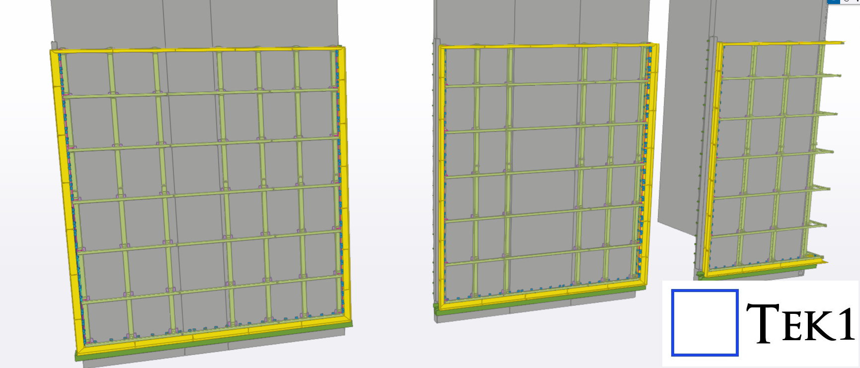
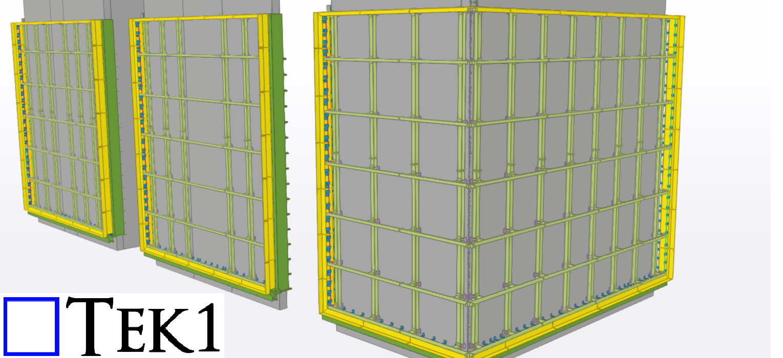
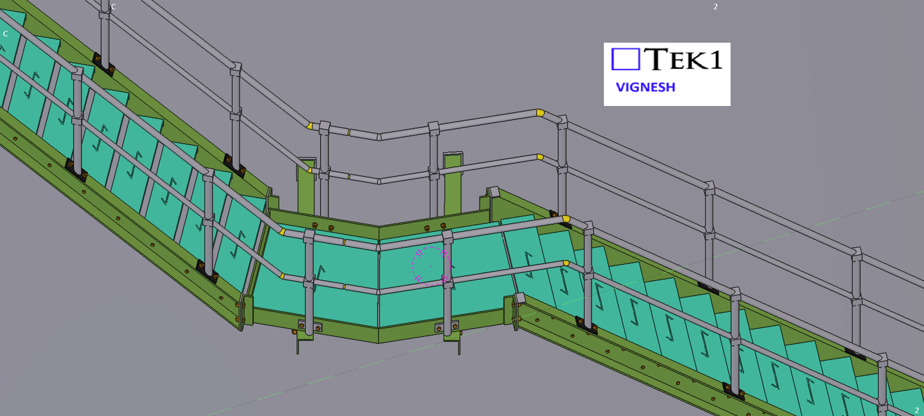
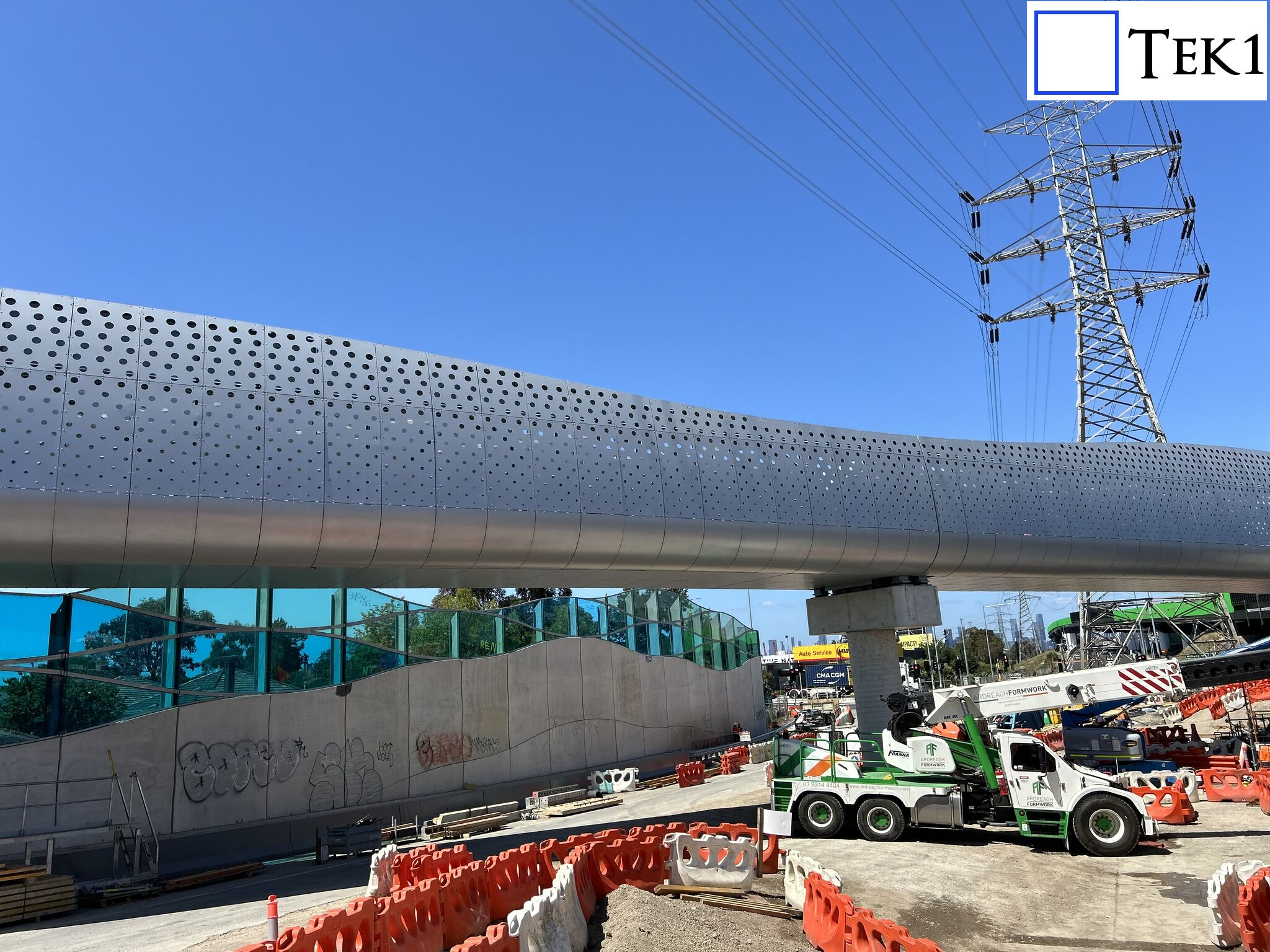
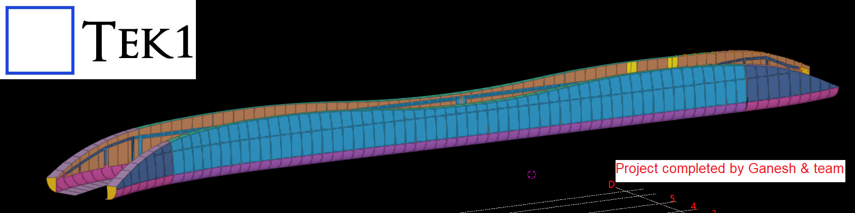
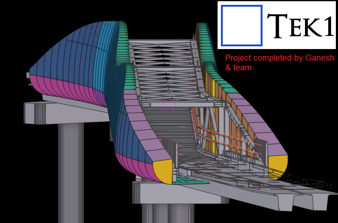
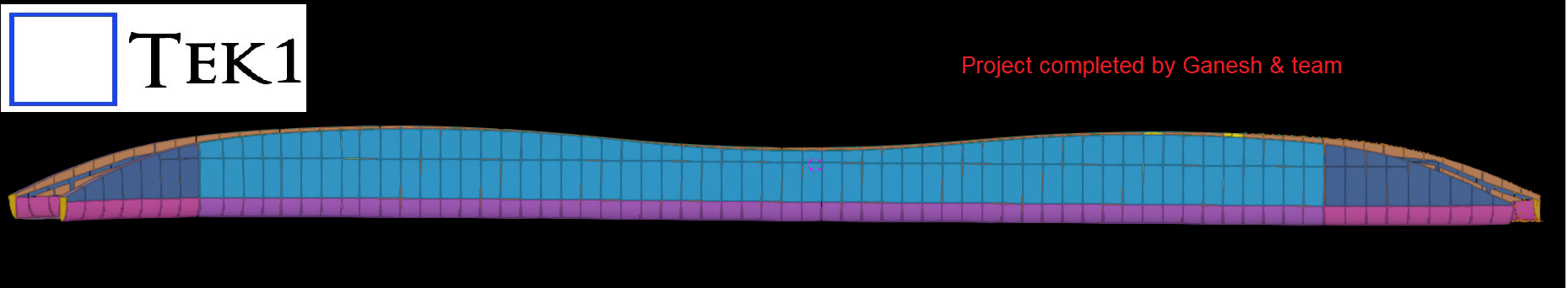
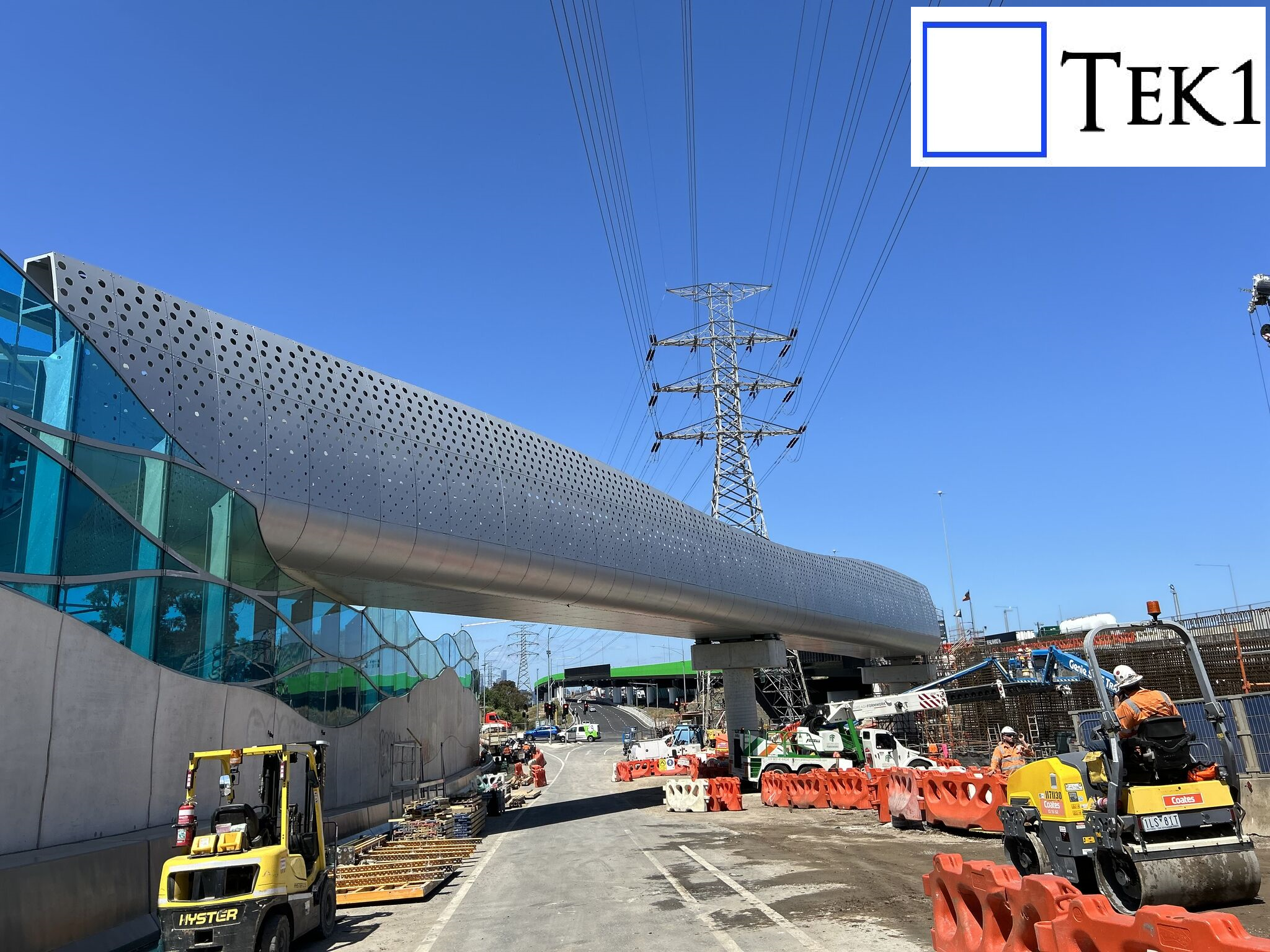
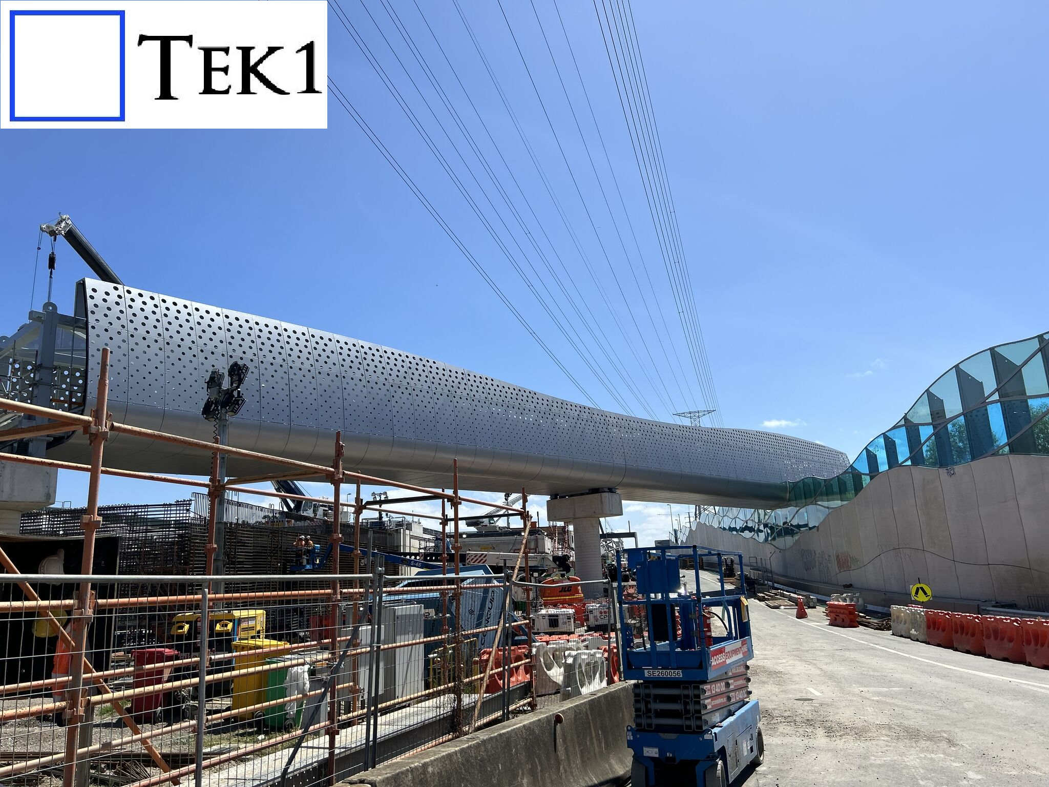
Tek1 recently completed a cladding project for a prominent organization in Australia. The project involved detailing cladding and its support system around a footbridge with unique challenges.
The footbridge featured curved ends, but these were not simple linear curves, making the design and detailing process particularly intricate.
Tek1 conducted numerous meetings with the client and engineers to finalize the cladding’s shape and ensure it met both aesthetic and structural requirements. This collaborative approach ensured the project’s success.
We hope you found our previous blogs on the Sydney Metro project insightful. If you missed them, check them out.
In this blog, I’d like to share another connection detail we proposed to the structural engineer on the Sydney Metro project
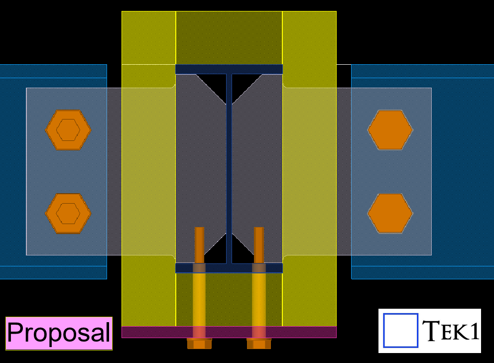
Since this is a metro project, fireproofing sheets are required on steel members as per the structural engineer’s specifications. However, the original connection details provided by the engineer were not feasible interms of installation of fireproofing sheets — they would make installing the fireproofing sheets difficult and time-consuming.
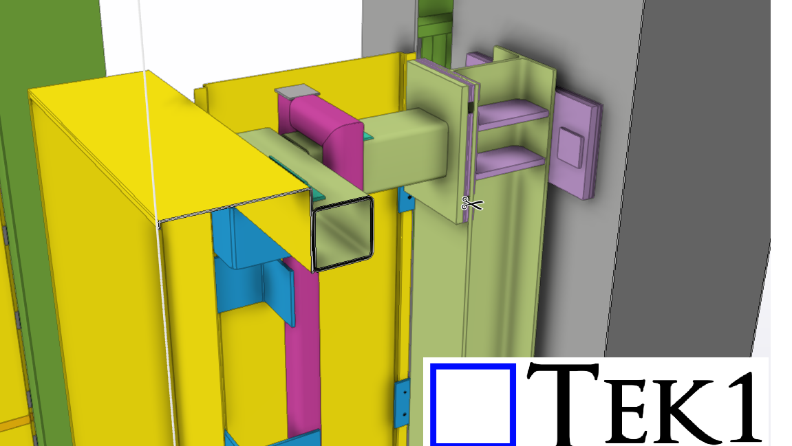
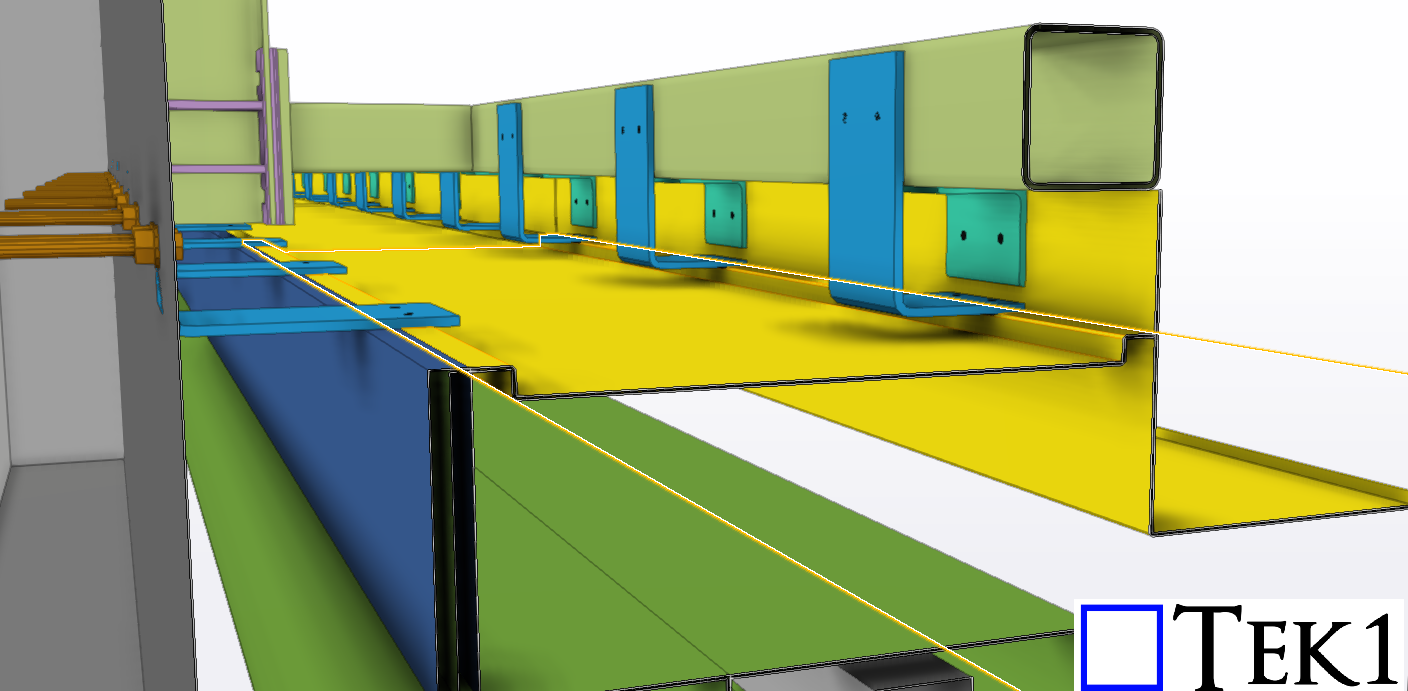
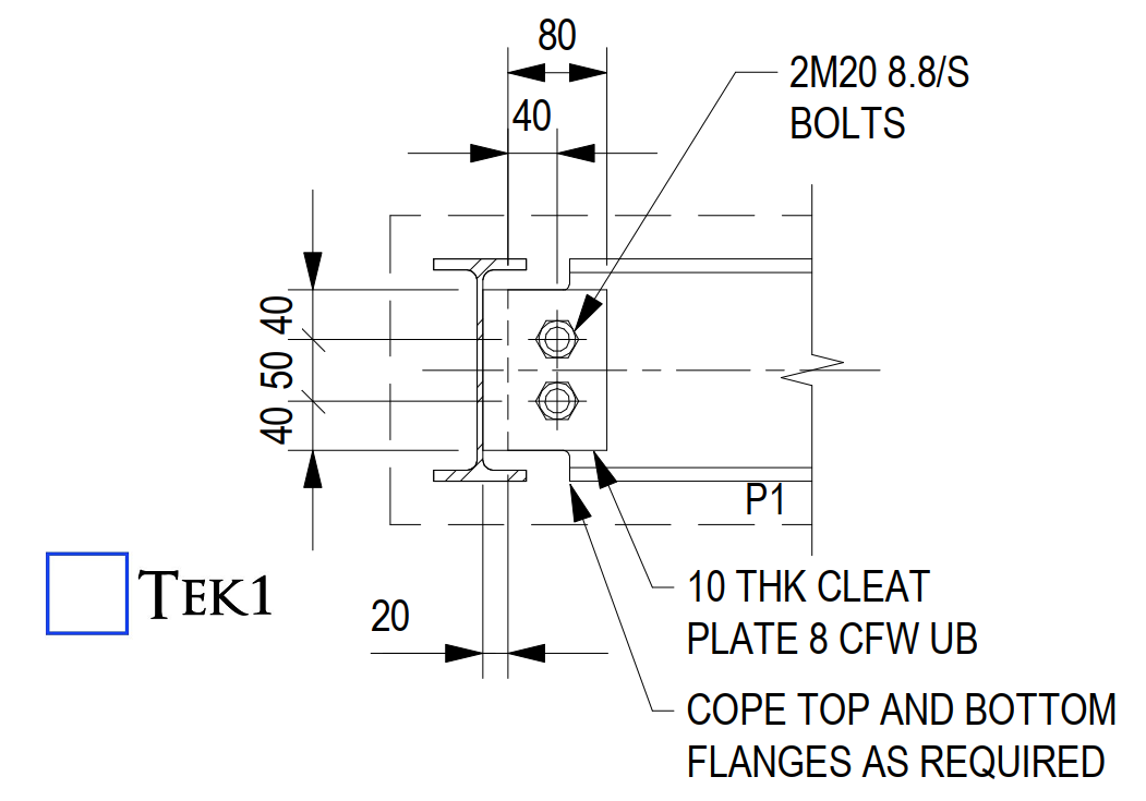
Please see the connection details below. These are the standard connection details typically used for the steel members.
However, applying these as-is may create difficulties during the installation of the fireproofing sheets.
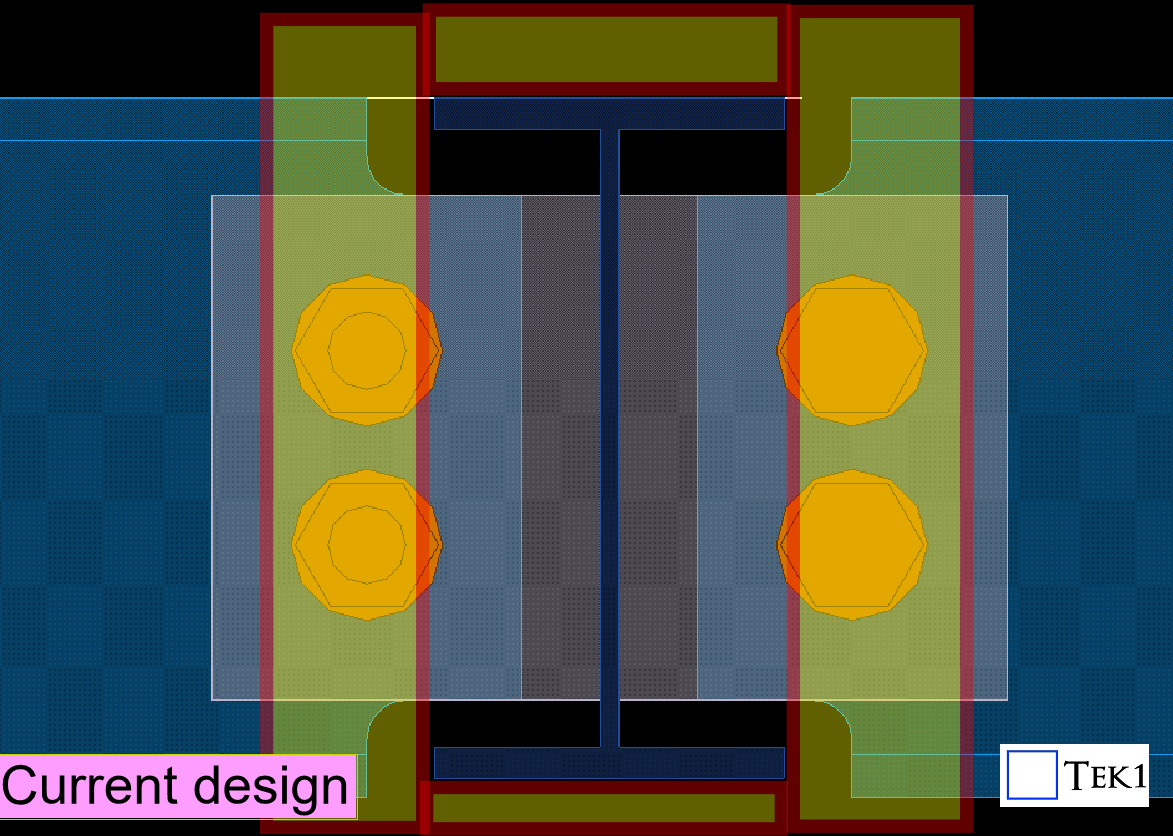
We identified this issue early in the detailing stage and proposed alternate connection details that would allow easier installation of the fireproofing sheets without compromising the structural requirement.
The engineer reviewed our proposal, suggested a few adjustments like thickness changes, and then approved our updated connection details.
Catching these issues early during detailing avoids major headaches later for installers and saves valuable time on-site
Stay with TEK1 for more updates on this sydney metro project
At TEK1, we believe great detailing is more than just precision—it’s about understanding real-world challenges and turning complexity into clarity.
The Challenge
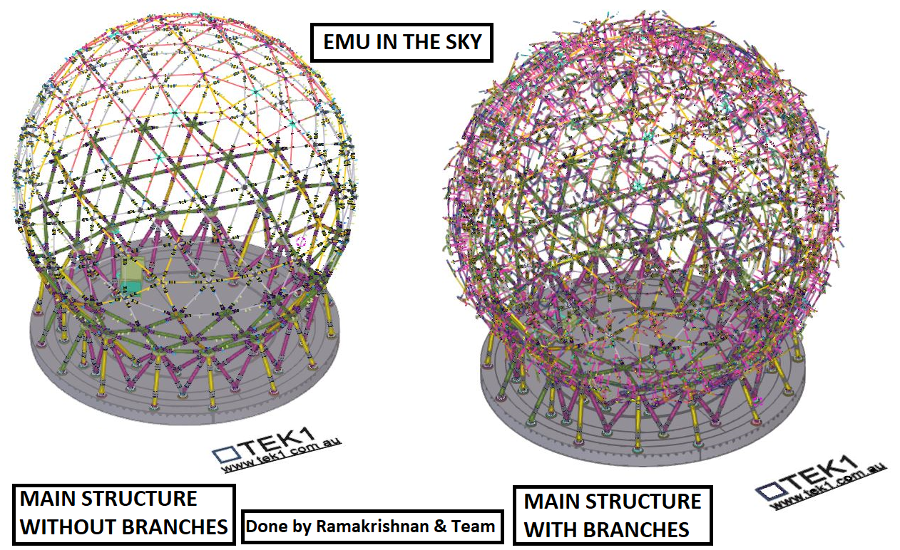
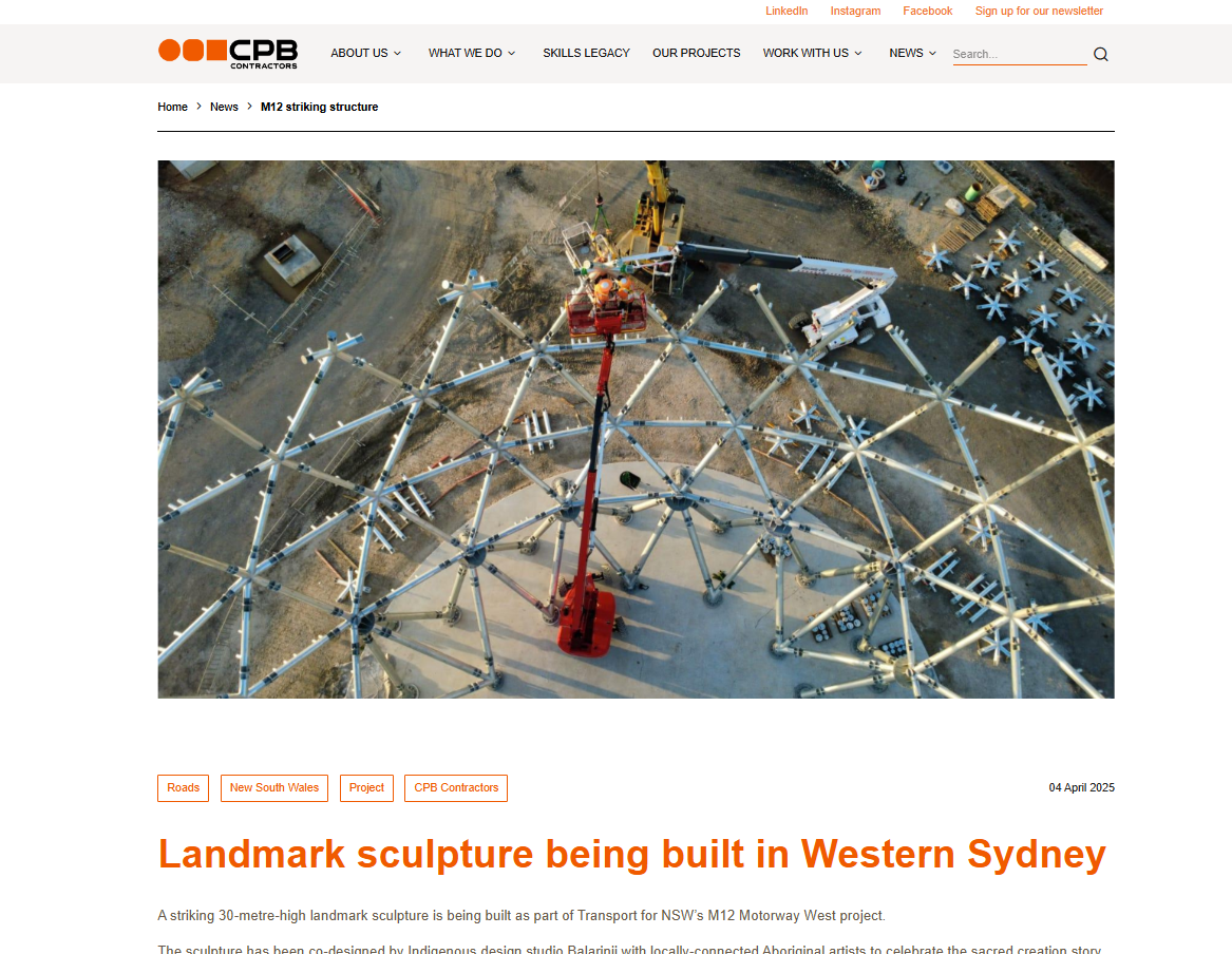
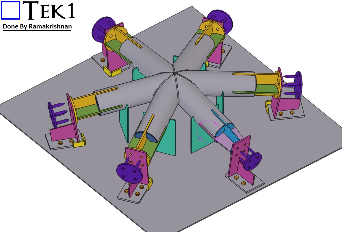
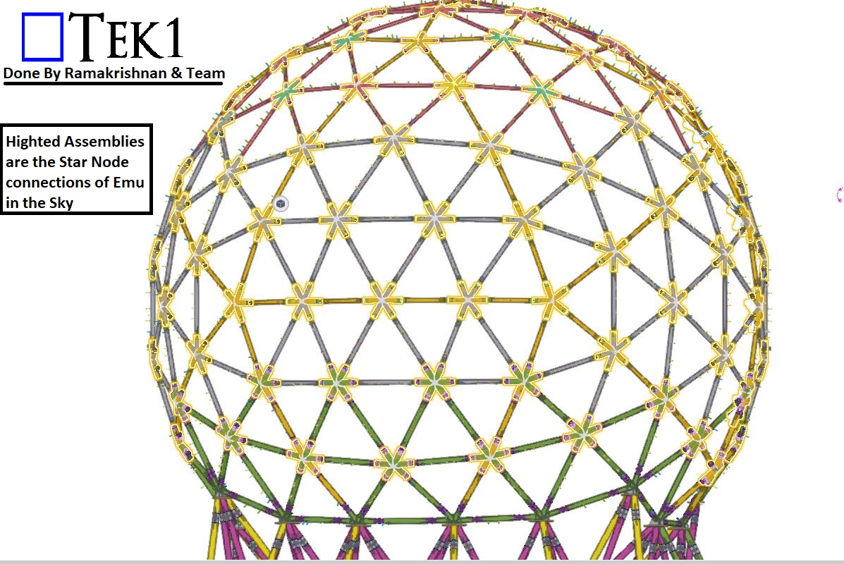
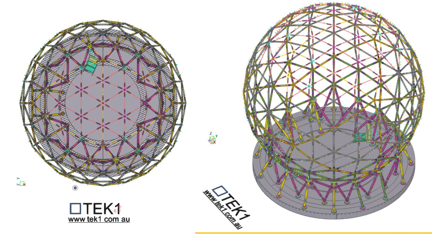
The Great EMU in the Sky project presented one of the most unique and technically demanding structures we’ve ever worked on—a 30-metre-wide globe made up of 128 intricate “star nodes” connecting the bracing members.
These nodes weren’t ordinary joints. Each featured 5 or 6 connection points and came in three different CHS sizes, with every arm set at unique, non-repeating angles.
For the fabrication team, this posed a significant challenge:
128 Complex Star Nodes, each with custom angles
Inconsistent geometries
Time-consuming and difficult to fabricate accurately
Even with precise 3D modelling, the practicality of fabrication was proving to be a serious bottleneck. Something had to change.
The Turning Point
That’s when TEK1 took the initiative.
Rather than simply delivering a model and walking away, we engaged directly with the fabricator to understand the issue from their perspective. We realized that even the most accurate detailing wasn’t enough—what the team needed was smarter, fabrication-friendly solutions.
The Solution
Our detailing team re-engineered how the star nodes were documented, presented, and ultimately fabricated. Key solutions included:
✅ Custom fabrication jig design: We developed a dedicated jig that allowed star nodes to be fabricated with greater ease and precision, regardless of the angle configuration.
✅ Standardized node sub-groups: We grouped similar nodes together to reduce variation and streamline production.
✅ Detailed templates: For common angle types, we provided accurate templates to guide fabrication.
✅ Visual fabrication aids: Clear drawings showing exact cuts, welds, and orientations for every node.
🤝 Stronger collaboration between design and workshop teams
Most importantly, the fabricators were able to work with confidence, knowing each node would come together exactly as intended.
Taking Detailing to the Next Level
This project reinforced one of TEK1’s core values: true excellence in detailing comes not just from precision—but from empathy. When we truly understand the needs of the people building the structure, we unlock practical, buildable solutions.
The Great EMU in the Sky is more than a globe—it’s a powerful example of what happens when detailers and fabricators work together as one team.
📢 Call to Action:
🚀 Have a complex structure or fabrication challenge? Partner with TEK1—where technical expertise meets buildability.
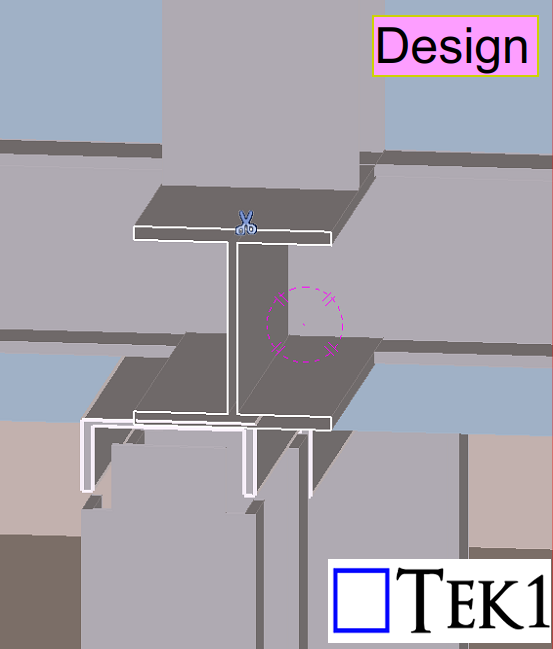
In this blog, we’ll share about a connection detail that we proposed to the engineer.
As per the design, a PFC beam needed to be supported by an I-beam above. However, in one location, the PFC beam was offset from the I-beam — and no connection detail was provided for this condition in the design drawings.
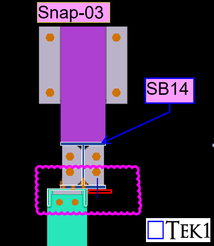
To address this, TEK1 proposed adding tab plates to connect the offset PFC beam securely. This solution maintained structural intent while resolving the missing detail.
The structural engineer reviewed our proposal and accepted it.See the below response from the engineer ‘Option shown in snap-03 accepted to maintain 2 bolts at each connection. Additional tab plate to be 80×10 FPBW to PFC. Bolt spacing to follow 140 gauge line of flange of SB14.‘
We go beyond drawings to ensure constructibility, reduce rework, and keep projects moving forward.Stay with TEK1 for more updates on steel detailing challenges and solutions in our upcoming blogs.