Category: Steel Detailing Projects

Steel Detailing projects Show case projects details by Tek1 pty ltd

  • How TEK1 Solved the Complicated Star Node Puzzle in Great EMU in the Sky

    How TEK1 Solved the Complicated Star Node Puzzle in Great EMU in the Sky

    At TEK1, we believe great detailing is more than just precision—it’s about understanding real-world challenges and turning complexity into clarity.

    The Challenge

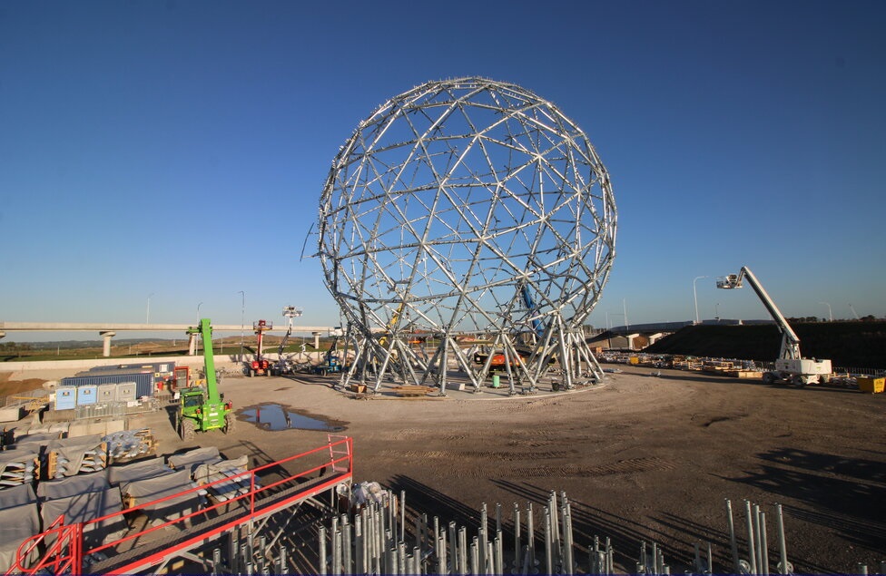
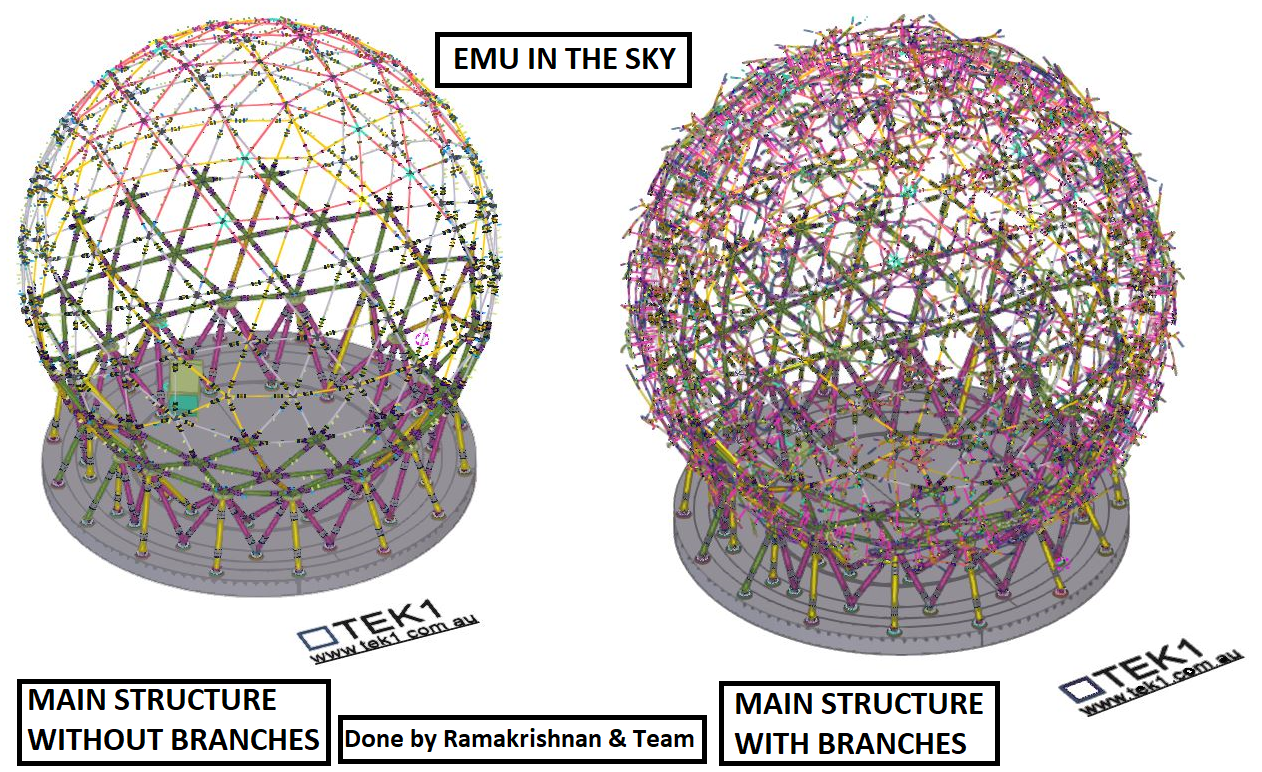
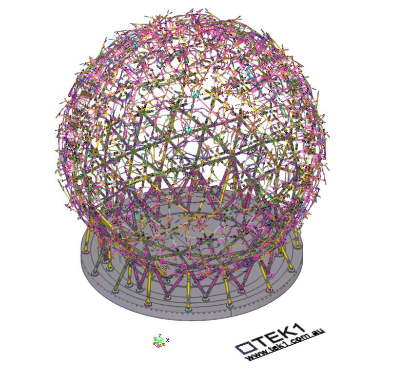
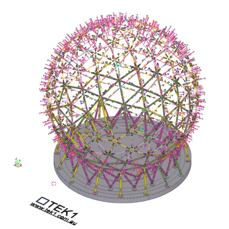
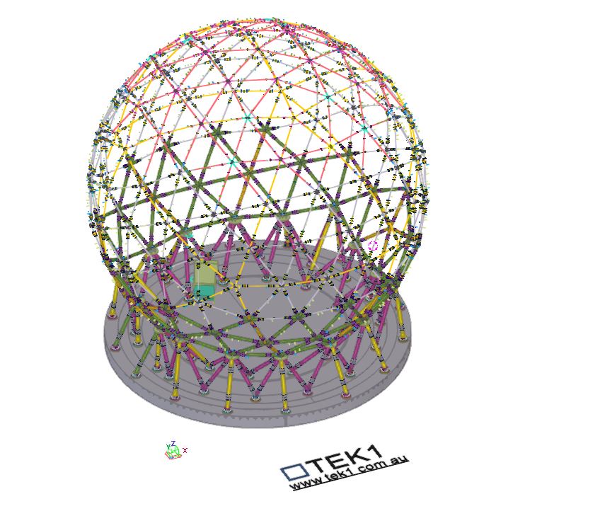
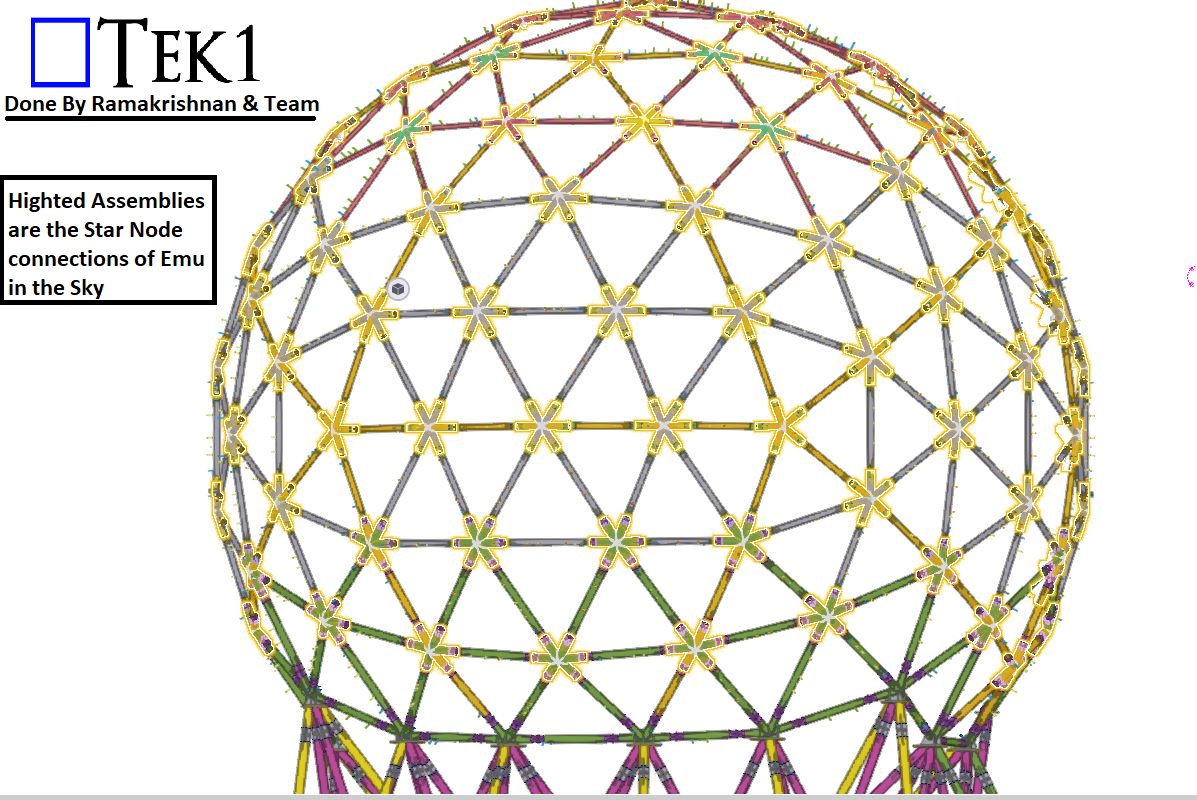
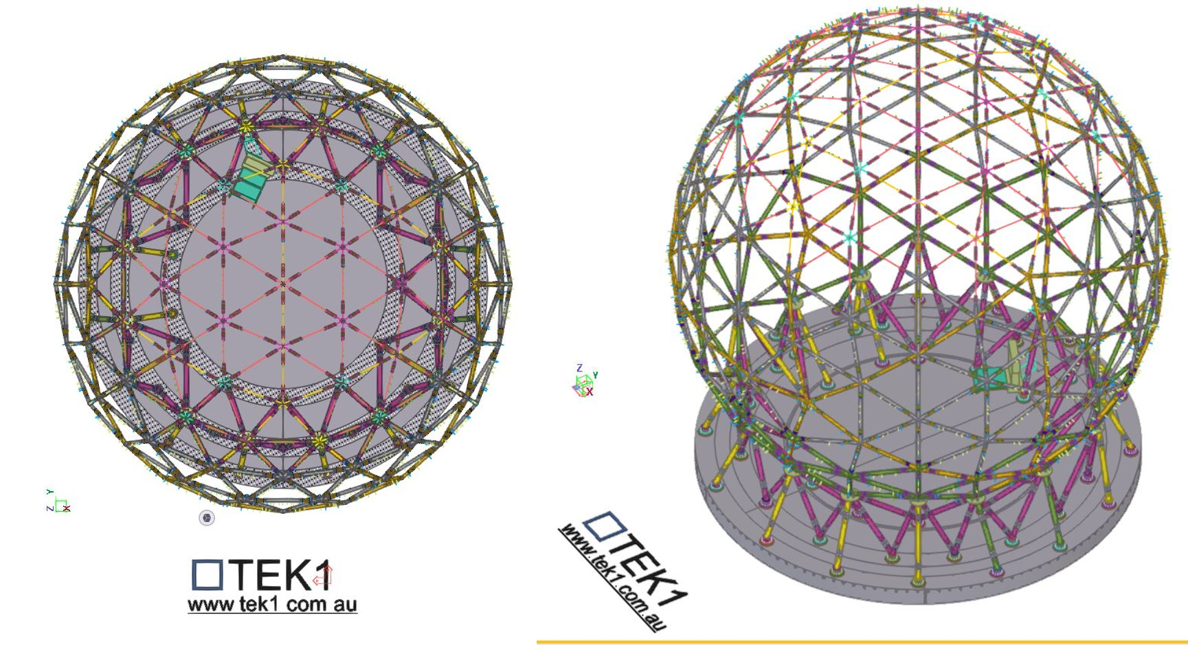
    The Great EMU in the Sky project presented one of the most unique and technically demanding structures we’ve ever worked on—a 30-metre-wide globe made up of 128 intricate “star nodes” connecting the bracing members.

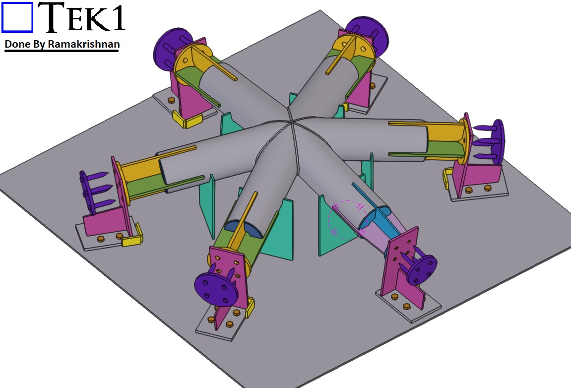
    These nodes weren’t ordinary joints. Each featured 5 or 6 connection points and came in three different CHS sizes, with every arm set at unique, non-repeating angles.

    For the fabrication team, this posed a significant challenge:

    • 128 Complex Star Nodes, each with custom angles
    • Inconsistent geometries
    • Time-consuming and difficult to fabricate accurately

    Even with precise 3D modelling, the practicality of fabrication was proving to be a serious bottleneck. Something had to change.
    The Turning Point

    That’s when TEK1 took the initiative.

    Rather than simply delivering a model and walking away, we engaged directly with the fabricator to understand the issue from their perspective. We realized that even the most accurate detailing wasn’t enough—what the team needed was smarter, fabrication-friendly solutions.

    The Solution

    Our detailing team re-engineered how the star nodes were documented, presented, and ultimately fabricated. Key solutions included:

    • Custom fabrication jig design: We developed a dedicated jig that allowed star nodes to be fabricated with greater ease and precision, regardless of the angle configuration.
    • Standardized node sub-groups: We grouped similar nodes together to reduce variation and streamline production.
    • Detailed templates: For common angle types, we provided accurate templates to guide fabrication.
    • Visual fabrication aids: Clear drawings showing exact cuts, welds, and orientations for every node.
    The Result

    • Faster fabrication times
    • 🎯 Improved accuracy and alignment
    • 🔁 Reduced rework and error rates
    • 🤝 Stronger collaboration between design and workshop teams

    Most importantly, the fabricators were able to work with confidence, knowing each node would come together exactly as intended.

    Taking Detailing to the Next Level

    This project reinforced one of TEK1’s core values: true excellence in detailing comes not just from precision—but from empathy. When we truly understand the needs of the people building the structure, we unlock practical, buildable solutions.

    The Great EMU in the Sky is more than a globe—it’s a powerful example of what happens when detailers and fabricators work together as one team.

    📢 Call to Action:

    🚀 Have a complex structure or fabrication challenge? Partner with TEK1—where technical expertise meets buildability.
  • TEK1’s Steel Detailing for Sydney Metro – Resolving Design Challenges – 3

    TEK1’s Steel Detailing for Sydney Metro – Resolving Design Challenges – 3

    We hope you found our previous two blogs on the Sydney Metro project insightful. If you missed them, check them out using the link below!

    In this blog, we’ll share about a connection detail that we proposed to the engineer.

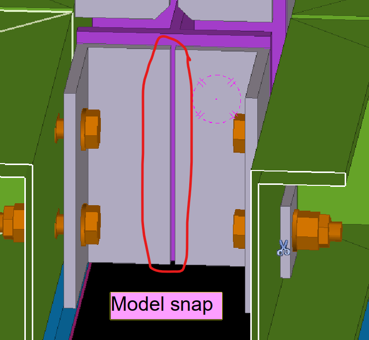
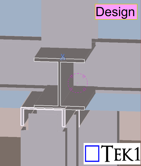
    As per the design, a PFC beam needed to be supported by an I-beam above. However, in one location, the PFC beam was offset from the I-beam — and no connection detail was provided for this condition in the design drawings.

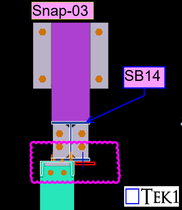
    To address this, TEK1 proposed adding tab plates to connect the offset PFC beam securely. This solution maintained structural intent while resolving the missing detail.

    The structural engineer reviewed our proposal and accepted it.See the below response from the engineer ‘Option shown in snap-03 accepted to maintain 2 bolts at each connection. Additional tab plate to be 80×10 FPBW to PFC. Bolt spacing to follow 140 gauge line of flange of SB14.

    We go beyond drawings to ensure constructibility, reduce rework, and keep projects moving forward.Stay with TEK1 for more updates on steel detailing challenges and solutions in our upcoming blogs.

  • TEK1 Brings the ‘Great Emu in the Sky’ Sculpture to Life for Sydney’s M12 Motorway

    TEK1 Brings the ‘Great Emu in the Sky’ Sculpture to Life for Sydney’s M12 Motorway

    TEK1 is proud to be part of an iconic project—the ‘Great Emu in the Sky’ sculpture, a monumental 30-meter-high emu nest that will stand as a cultural landmark along Sydney’s M12 Motorway.

    A Symbol of Dharug Heritage

    The peanic structure celebrates the Dharug Community’s sacred creation story of the Great Emu constellation.

    A Landmark Visible from Land & Sky

    Positioned for maximum visibility, the sculpture will be seen by:

    • Road users
    • Pedestrians
    • Sydney Metro passengers
    • Even planes approaching and departing Sydney Airport

    Blending Art, Culture & Engineering

    The steel artwork will take on different forms depending on the time of day and viewing angles:We look forward to seeing this one-of-a-kind sculpture take its place in Sydney’s landscape, honoring history while welcoming the future.

    • By day, it will resemble an emu nest, crafted from signature steel “sticks” that reflect the natural landscape and traditional materials of the Dharug people.
    • By night, it will illuminate and reveal two emu forms, visible only from certain perspectives—mirroring the Great Emu constellation as it shifts throughout the six Aboriginal seasons.

    TEK1’s Role in Detailing the Sculpture

    A lot of technical challenges were navigated to ensure that this complex structure, could be fabricated and erected, cheaply and efficient. We will document this on our blog if you’re interested.

    Please refer to the below video which represents the various stages of on-going erection

  • SYDNEY METRO CITY & SOUTHWEST TUNNELGRC PANELS & ITS BRACKET

    SYDNEY METRO CITY & SOUTHWEST TUNNELGRC PANELS & ITS BRACKET

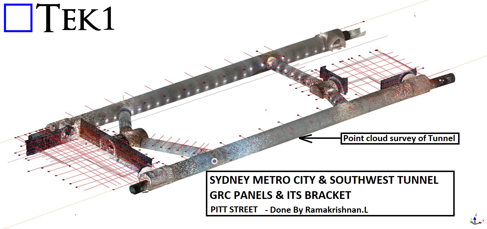
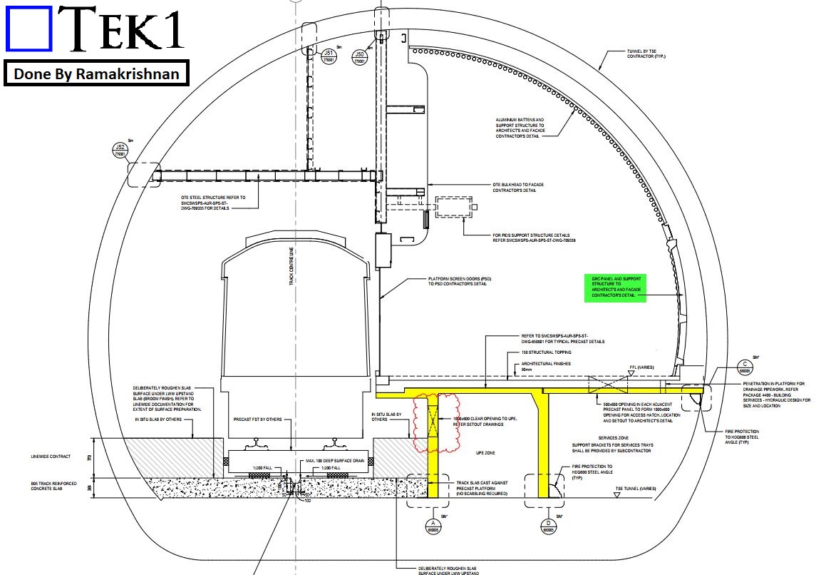
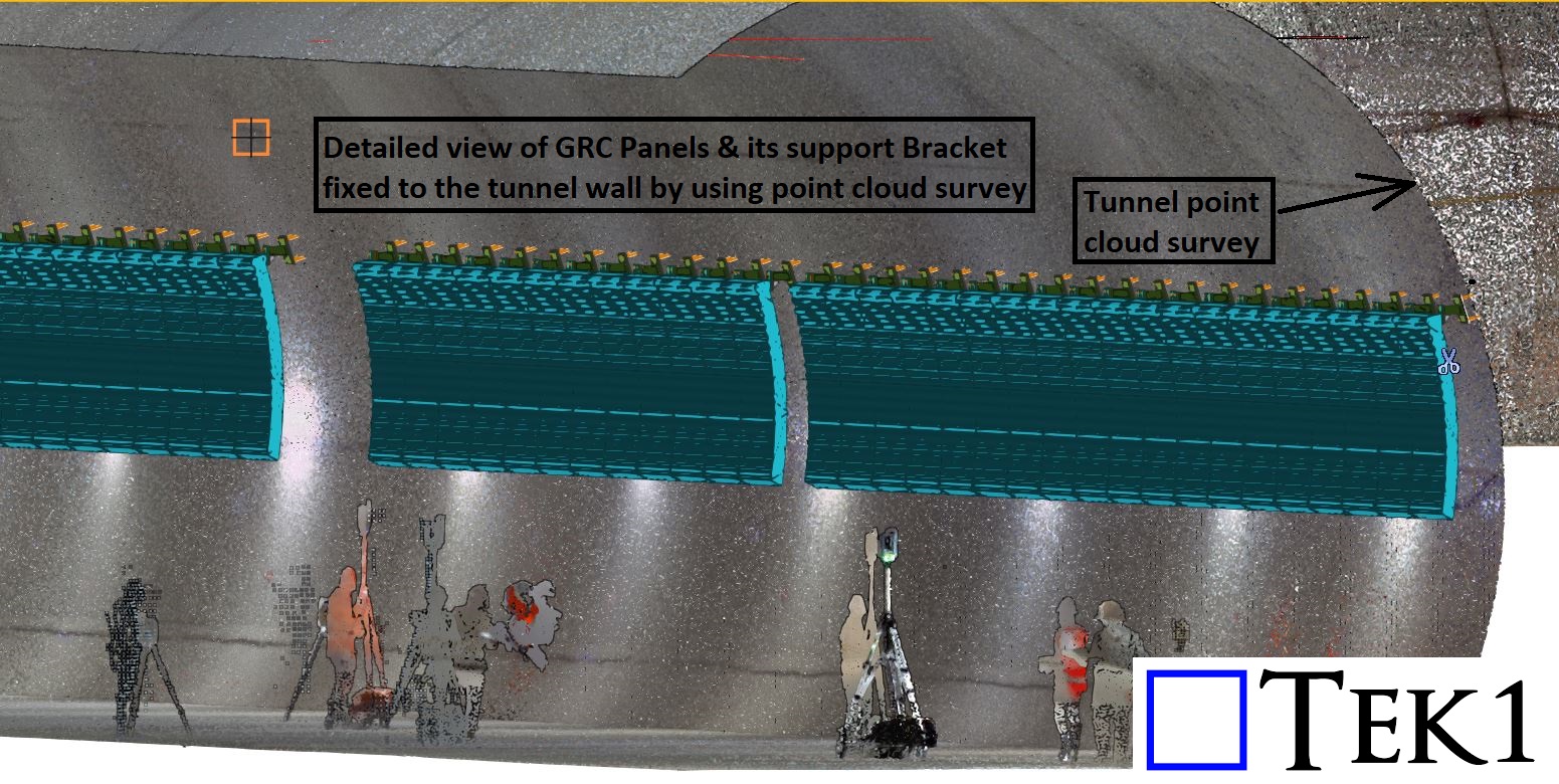
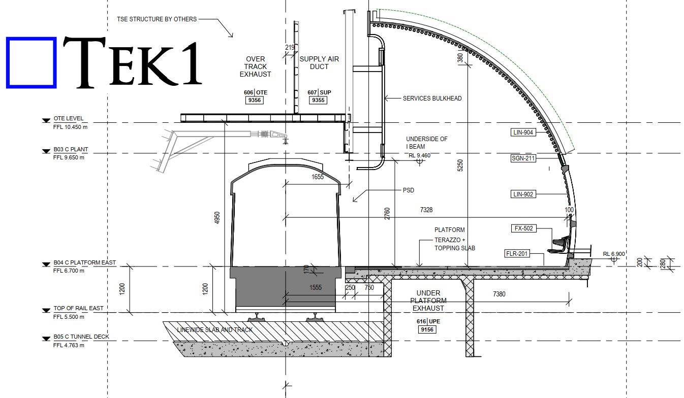
    TEK1, we recently had the opportunity to detail GRC panel brackets for a section of the Sydney Metro Tunnel, utilizing a point cloud survey to ensure precise alignment and installation.

    Project Overview

    The client provided a point cloud survey of the tunnel, allowing us to accurately determine the placement of GRC panels and their supporting brackets. Since tunnel walls are rarely perfectly straight—often featuring irregularities, ups, and downs—extra attention was required to ensure each bracket was positioned correctly for a seamless fit.

    Challenges & Solutions

    Efficient Coordination – By leveraging point cloud technology, we minimized potential site adjustments, streamlining the installation process for our client.

    As-Built Adjustments – The natural deviations in the tunnel wall’s shape meant that standard placements wouldn’t work. The point cloud data helped us fine-tune the bracket positions to match real-world conditions.

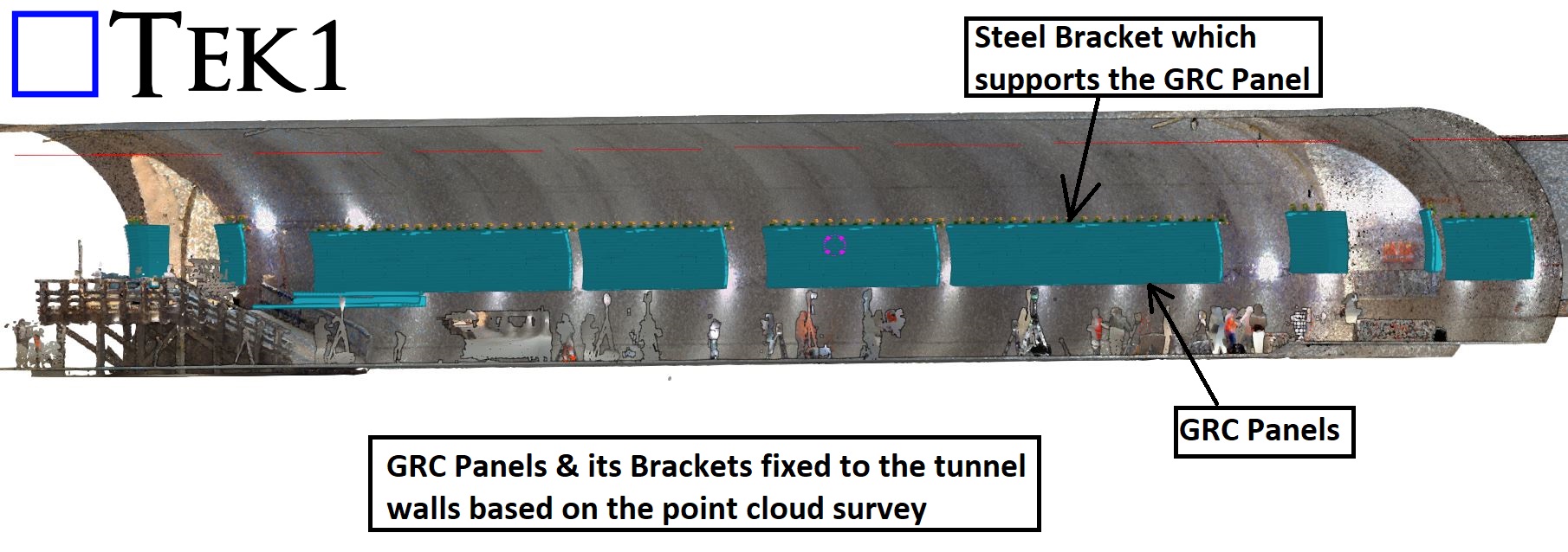
    Precision Detailing – Each steel bracket was meticulously detailed to accommodate the GRC panels, ensuring a secure and uniform installation.

    Conclusion

    Working with as-built tunnel walls requires high accuracy and adaptability, and this project was a great example of how TEK1 effectively integrates advanced technologies like point cloud surveys into our detailing process.

    Check out the snapshots below to see how the GRC panels are securely fixed to the tunnel wall using custom steel brackets.

  • TEK1’s Steel Detailing for Sydney Metro – Resolving Design Challenges – 2

    TEK1’s Steel Detailing for Sydney Metro – Resolving Design Challenges – 2

    In the last blog in Sydney metro project , we discussed about the design issue regarding angle weld. https://www.tek1.com.au/steel-detailing/tek1s-steel-detailing-for-sydney-metro-resolving-design-challenges-1/

    Here we are going to discuss about the member placement issue.

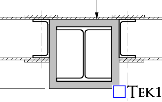
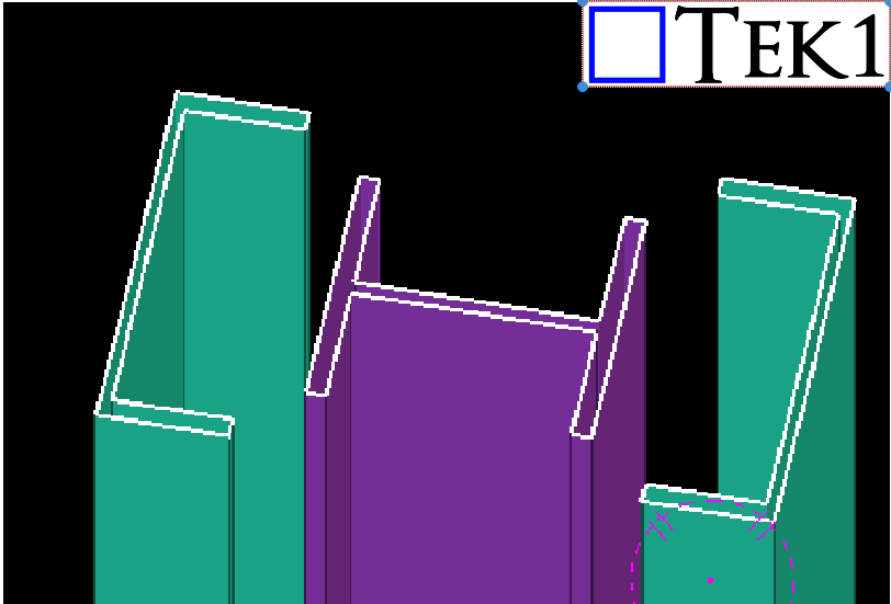
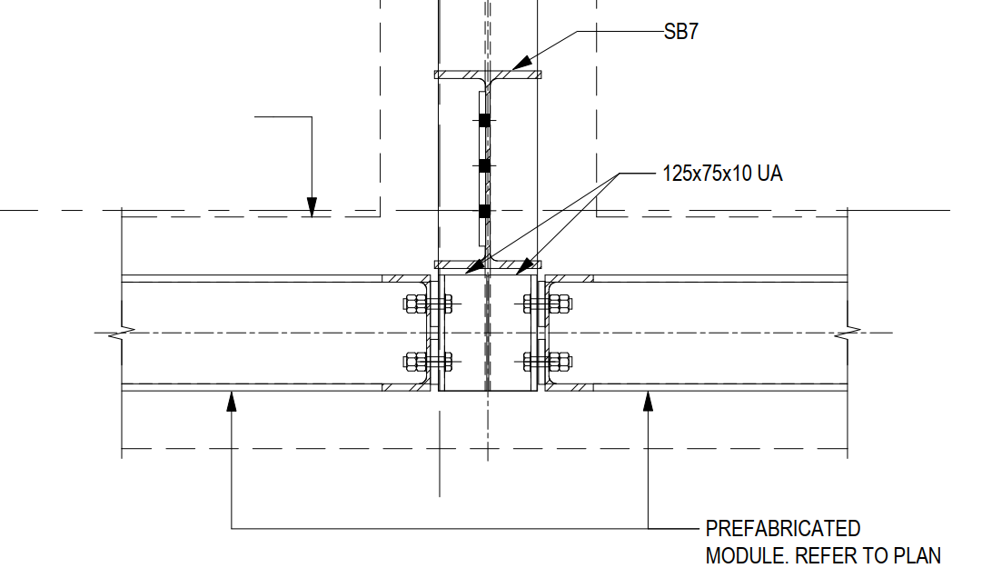
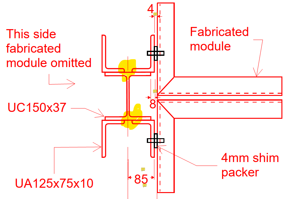
    The design specified two PFCs on both sides of a column.Column was surrounded by fireproofing sheets. However, the PFC flanges clashed with the fireproofing sheets, making installation difficult. Additionally, the bolts connecting the PFCs would interfere with the fireproofing.

    To resolve this, TEK1 planned a simple yet effective adjustment—changing the orientation of the PFCs. This allowed for seamless fireproofing installation without compromising the structural integrity.

    If we have followed the design , then the erection team will have difficulties to provide the fireproofing sheets.By identifying and addressing potential clashes early in the detailing process, TEK1 saved significant time and costs for the client, ensuring a smooth execution on-site.

    Stay with TEK1 for more updates on steel detailing challenges and solutions in our upcoming blogs.

  • Erection Issue Eliminated Through Suggested Changes in the Splice Connection During Detail Engineering

    Erection Issue Eliminated Through Suggested Changes in the Splice Connection During Detail Engineering

    Issue Identified During Detail Engineering

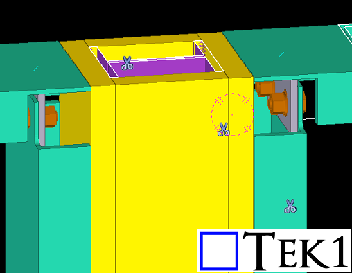
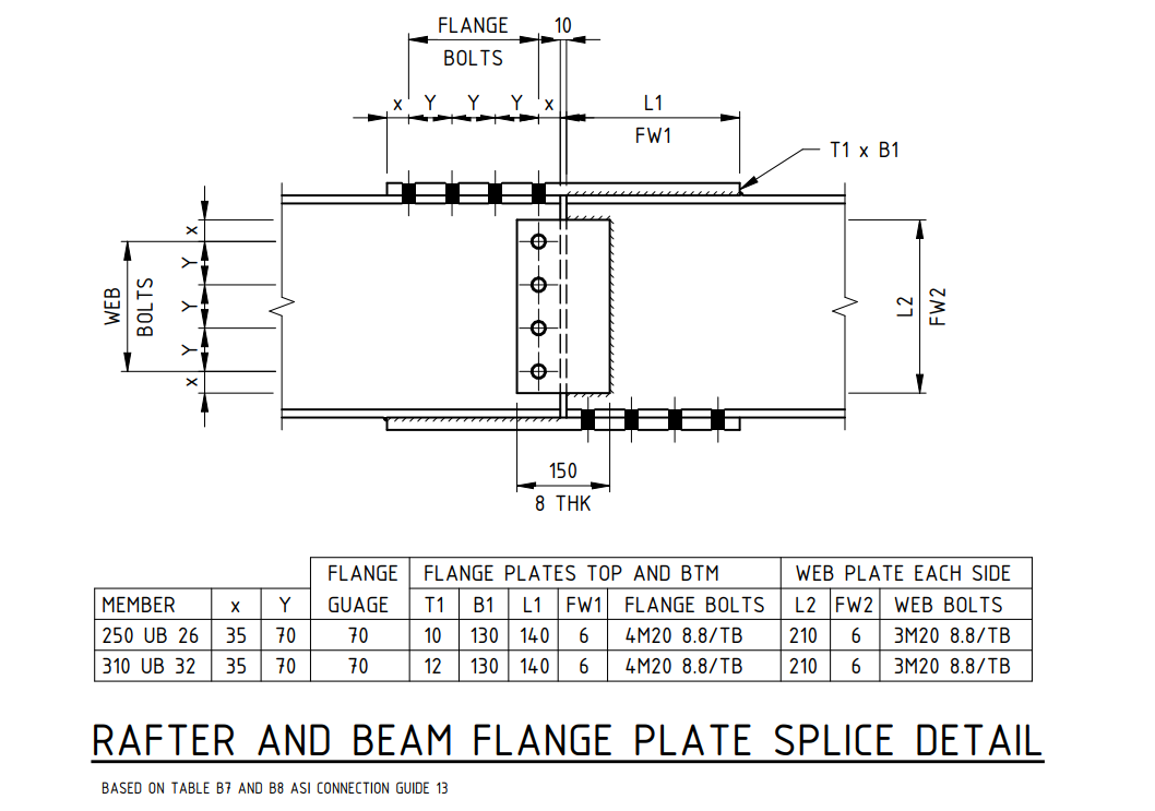
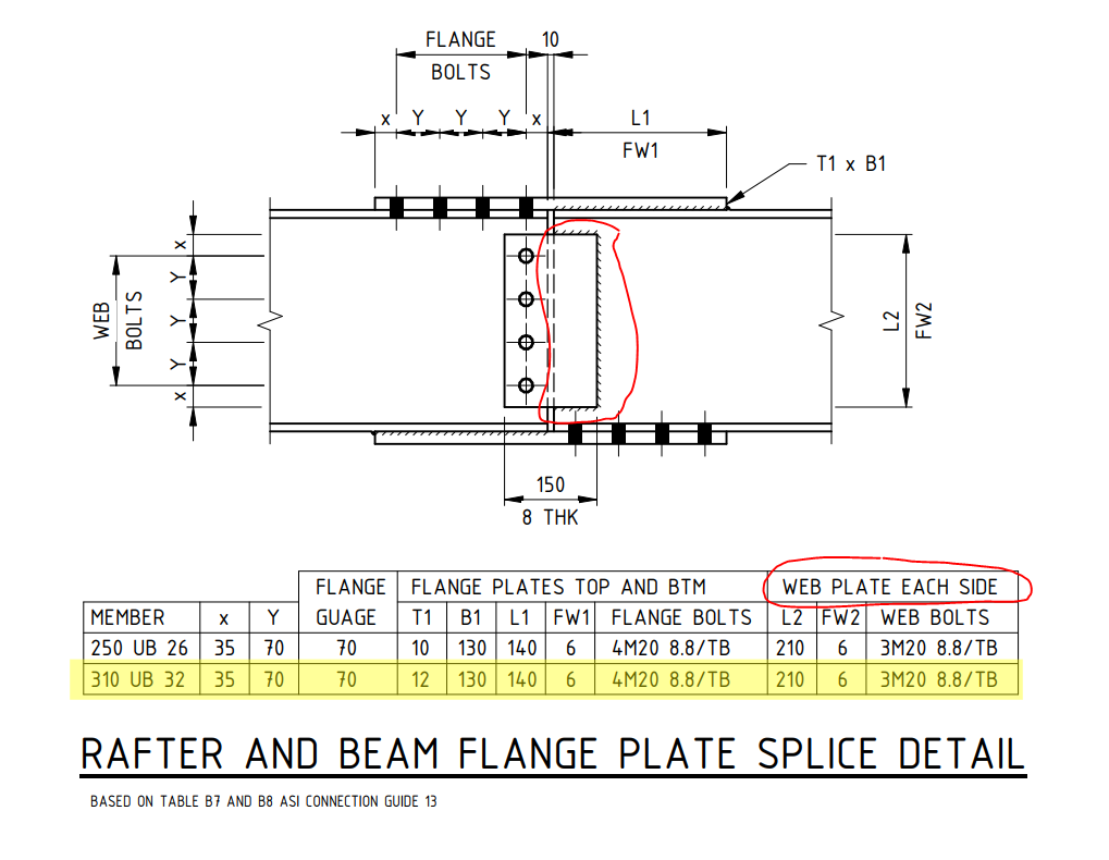
    • During detail engineering, it was identified that the design specifies both-side web plates, with shop weld on one side and field bolts on the other.
    • This would have created a field erection issue, as the shop-welded web plate on both sides prevents secondary beam placement.

    Proposed Solution: Fully Bolted Connection

    • Use bolted connections on both sides instead of welding one side.
    • This allows the web plate to be shipped loose, making field installation easier.
    • At the site, the secondary beam can be placed first, followed by the web plate installation and bolting.
    • Factory-drilled holes ensure precise alignment and better quality.
    • Eliminates on-site welding hazards and inspection issues.

    Client Approval

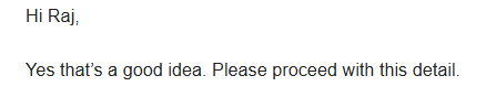
    • The client accepted the suggestion due to its practical benefits and ease of installation.
    • The change improves efficiency, cost-effectiveness, and safety.

    Conclusion

    • Switching from welded-bolted to fully bolted improves constructability.
    • Ensures stronger, safer, and more efficient structural connections.
    • Small design changes can greatly impact project success.
  • TEK1’s Steel Detailing for Sydney Metro – Resolving Design Challenges – 1

    TEK1’s Steel Detailing for Sydney Metro – Resolving Design Challenges – 1

    TEK1 is currently engaged in steel detailing for the Sydney Metro project, working with a reputed organization in Australia. During the detailing process, we have encountered several design challenges. Here, we will share one such issue and how we resolved it.

    The Issue

    A design required two unequal angles welded to a small hanger with 10mm packer plates. This left insufficient weld space, making fabrication tough.

    Recognizing this issue early, we raised a query with the concerned team. Our initial proposal was to cut both angles to create the required weld space.

    After reviewing our concern, the team suggested an alternative solution that involved reducing the packer plate thickness from 10mm to 4mm. This adjustment allowed for a 6mm weld clearance on both sides without significantly affecting the design.

    If this issue had gone unnoticed and we had followed the original design, it would have caused complications for both the fabricator and the designer. By identifying the problem early and addressing it proactively, we saved time and costs for the client.

    Stay Tuned for More Insights

    This is just one example of how TEK1 ensures seamless steel detailing by resolving design issues efficiently. Stay with TEK1 for more updates on steel detailing challenges and solutions in our upcoming blogs.

  • Melbourne Airport Gantry

    Melbourne Airport Gantry

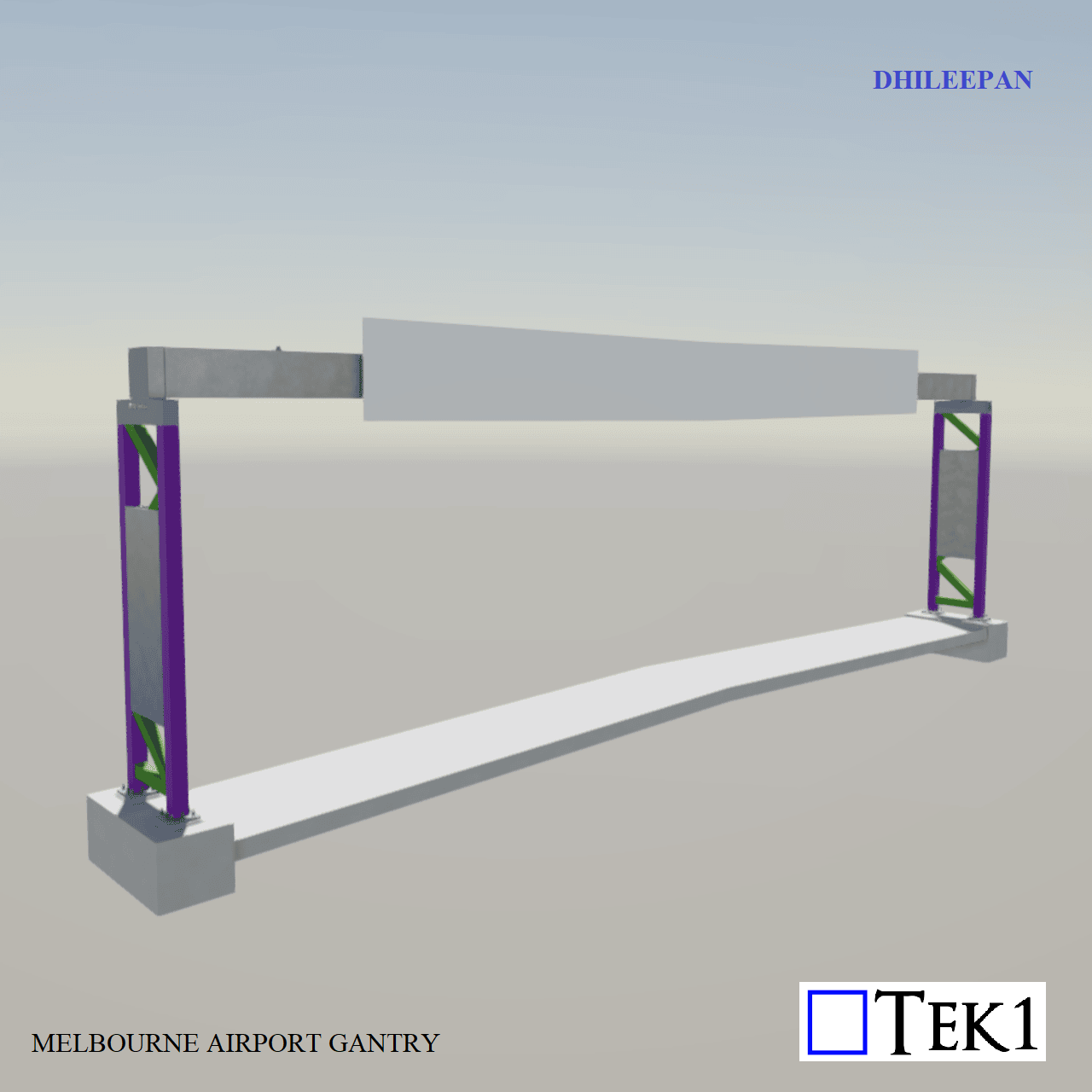
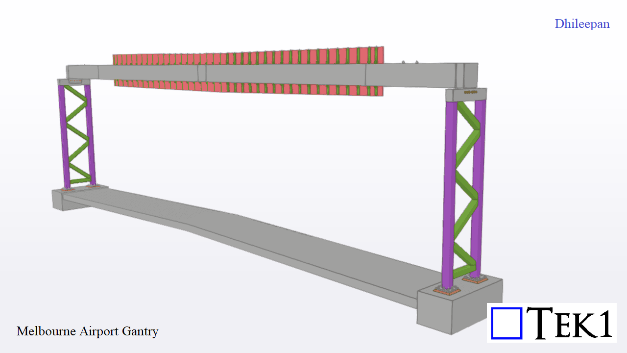
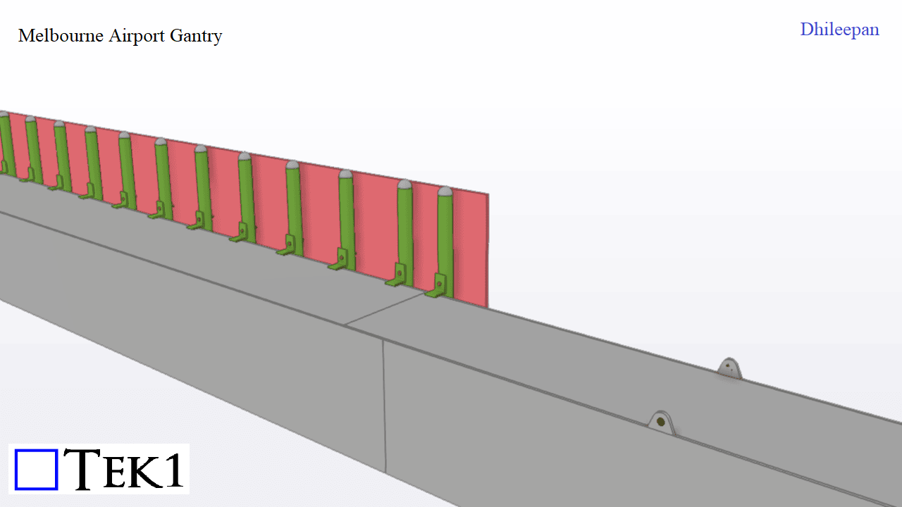
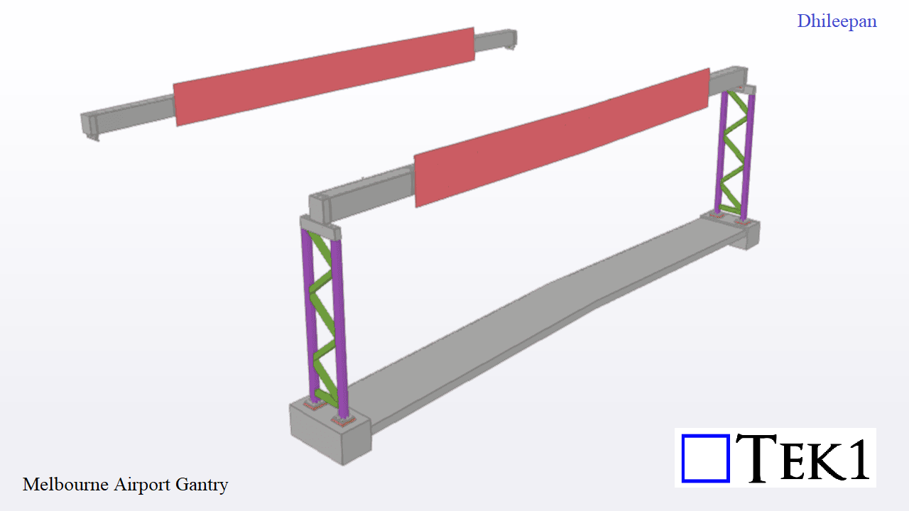
    At Melbourne Airport, a gantry supporting a signboard spans 26 meters between laced columns without intermediate supports. The box gantry alone weighs 8 tonne. Since the gantry would bend because of to its self weight, pre-camber of 170mm was provided at the middle.


    For accurate representation, two models were created: one with pre-camber for assembly drawings and another without for general arrangement (GA) drawings. This approach ensures clarity in fabrication and erection, maintaining structural integrity while achieving the desired final alignment.

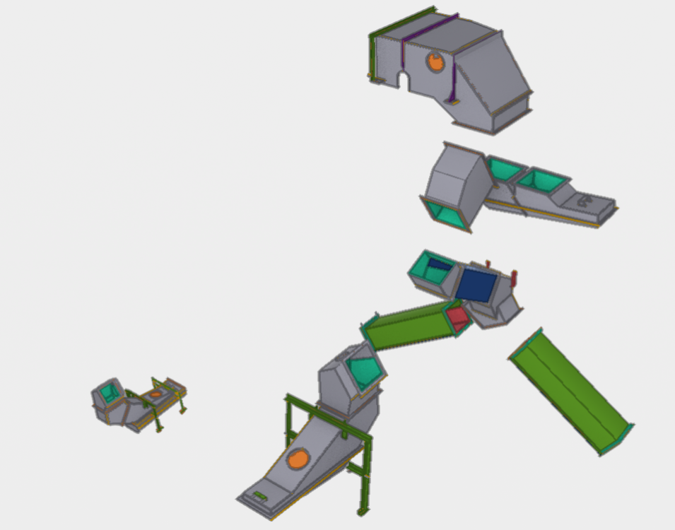
  • Grain Chutes

    Grain Chutes

    Input information was an Inventor model and pdf drawings

    We have extracted the information from inventor, cross checked with pdf drawings, Checked constructurability, Resolved design details so that items can be fabricated at lowest cost.

    These chutes were submitted for approval, and was approved without any issues.

    Eventhough these chutes are for grain transfer, mining projects have similar requirements.

    CHUTES