If you are detailing Aluminium or SS sections always confirm the section profiles.
If you model without that confirmation, there is good chance that you will be spending additional hours and it will be wasted time for all
This is a blog to give tips and tricks to Tekla users. We will bring you the best and the latest in Tekla and structural steel detailing
If you are detailing Aluminium or SS sections always confirm the section profiles.
If you model without that confirmation, there is good chance that you will be spending additional hours and it will be wasted time for all
CNTRL + RIGHT CLICK to set start point
Press X, Y, or Z to Lock the co ordinate as the need may be
Save time in modelling
Tekla Structures’ object lock is a crucial feature, particularly in multi-user environments like Tekla Model Sharing, designed to prevent accidental modification and control access to specific model objects and drawings. It acts as a protective measure to maintain model integrity and streamline collaborative workflows.
Here’s a breakdown of how it works and its key aspects:
Purpose of Object Locks:
How Object Locks Work:
XS_OBJECTLOCK_DEFAULT advanced option). This means only users from that organization can modify them.Important Considerations:
In essence, Tekla Structures’ object lock is a powerful tool for managing and protecting your model data, especially in complex, collaborative projects. It provides a layer of security and control that is essential for efficient and error-free structural modeling.
Expert detailiing of spiral stair with plate stringers.
Clear drawings and set outs for easy fabrication.
Here is and example.
Tek1 has the experience detailing different types of spiral stairs.
There are challenges for the fabricator. Good drawings help to reduce the issues the fabricator will be facing.
If you want the Tekla Model for this email me.
Make sure there is sufficent clearance for welds.
The cost of not providing weld clearance is significant.
These type of errors chips away at our credibility
Lysaught provides different types of brackets.
Whe you are modelling choose the appropriate types
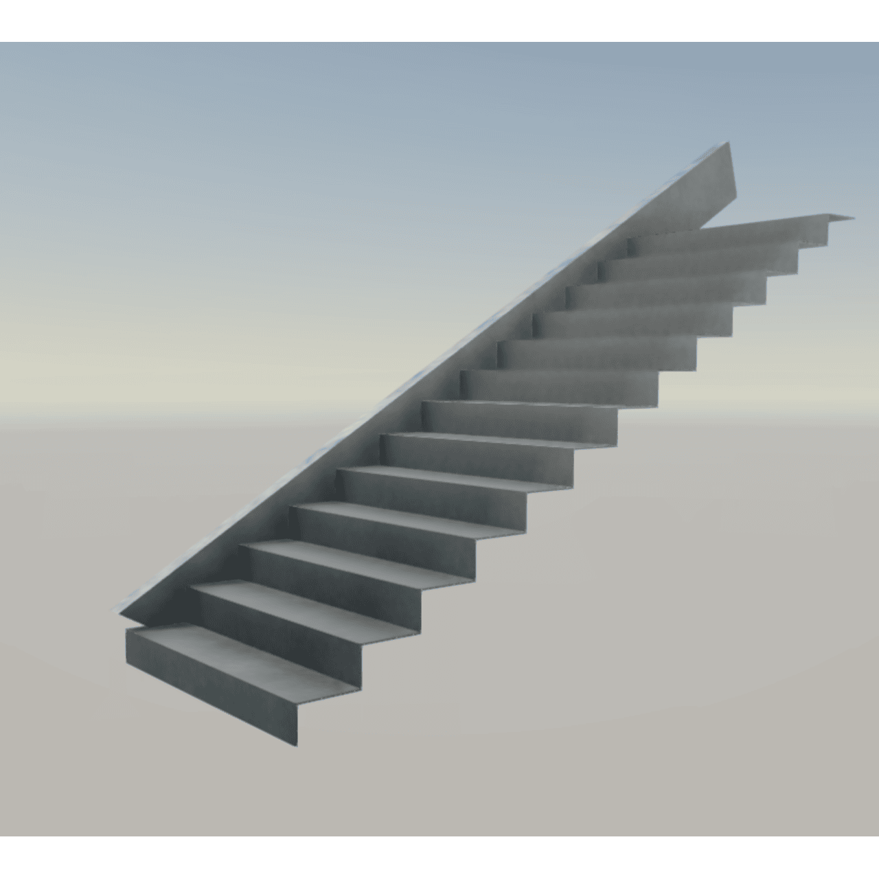
Imagine you’re reviewing a staircase drawing, and you see this note:
“8 THK CONTINUOUS FOLDED PLATE TREADS AND RISERS.”
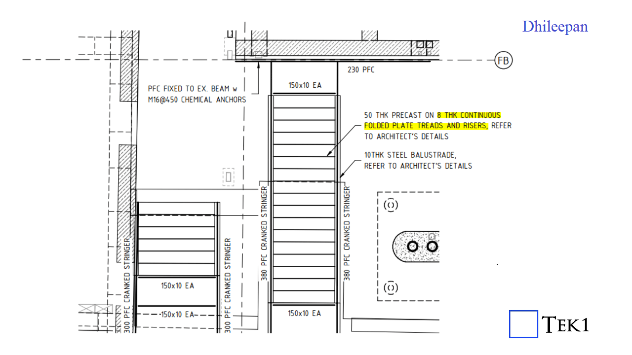
Sounds fine, right? But here’s the catch—is it actually possible to fold a single plate continuously for an entire stair flight? 🤔
A plate cannot be folded continuously to form multiple stair treads and risers because:
Instead of one continuous folded plate, each tread and riser should be a separate, single-folded plate. These individual elements can then be welded or bolted together to form a strong and practical staircase.
So next time you see a similar detail, take a closer look—is it actually buildable?
If your bolt report has ferrule bolts, then you have to specify what is the Bolt Dia and Length of the Bolt dia. Also you must specify no nut required.
The other thing to note is that, You cannot give extra length. Your bolt length should be a bit less than the Thread in the ferrule + the washer + the material to be bolted.
If we nomintate extra length, then the Bolt will bottom out on the ferrule.
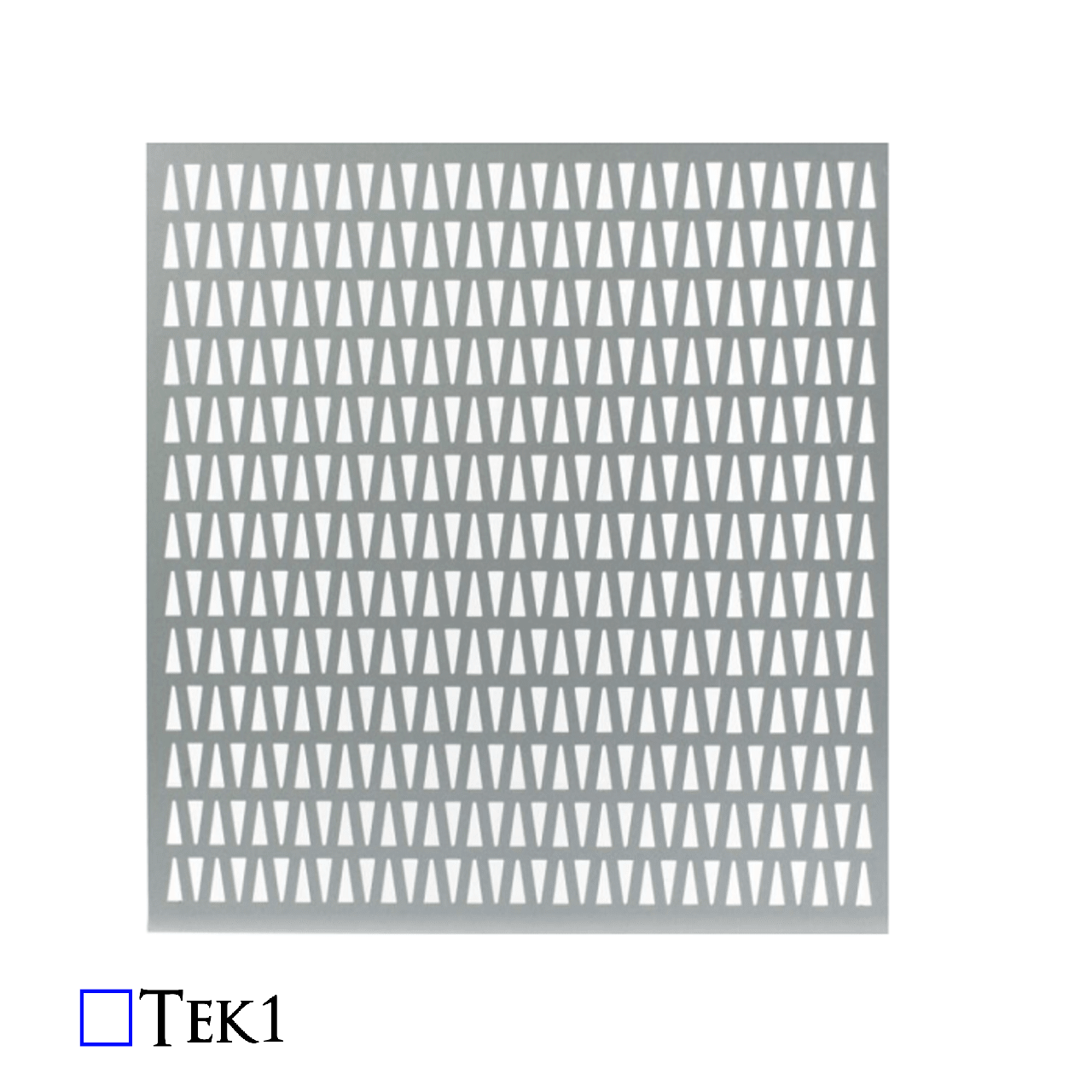
When working with elements like cladding plates, balustrade infills, decorative panels, and chequer plates, the approach to modelling them differs significantly from that used for standard structural plates. Ensuring accuracy in these cases hinges on a thorough understanding of working points and the rotation property, which are essential for ensuring the correct orientation of the visible side when generating drawings or DXF files.
It might seem simple to assume that these sheets can be flipped or rotated as needed after they are cut. However, this is a common misconception that can lead to significant errors during fabrication. The key to avoiding such issues lies in setting up the working points correctly, particularly when dealing with intricate designs or surface finishes.
Take a stair panel, for example. If the panel features any patterns or surface differences, the working point must run in the direction from left to right when facing the stair panel. Additionally, the rotation must be set to either “top” or “front”—never “bottom” or “back.” This ensures that the visible side of the panel is correctly positioned.
Even in cases where the pattern is symmetrical or there appears to be no pattern at all, the orientation of the face of the sheet is crucial. It’s easy to think that since the machine will cut the plate according to the DXF file, it doesn’t matter how the drawing is flipped or rotated. However, this is where problems can arise.
During the cutting process, the machine can leave minor marks on the material. These marks are typically left on the non-visible side of the sheet. Therefore, it’s critical to feed the sheet into the machine with the correct side facing outwards. If not, the marks could end up on the visible side, compromising the aesthetics of the final product.
Proper modelling and careful consideration of working points and rotation properties are essential when dealing with cladding plates, balustrade infills, decorative panels, and chequer plates. By ensuring the visible side is correctly oriented from the start, you can avoid costly mistakes and ensure a high-quality finish.