Contour Marking: It is an information written in an NC file that passes information to the NC machine on the layout and the parts that are welded together.
Requested from client
Tek1 do care about every client so we thought of seeking the help of Trimble Connect warehouse and found an plugin suiting the criteria.
Convertor plugin found on Warehouse
How the Convertor Works
The convertor converts all the NC files to DXF. By default it converts the members in Front View. To obtain the contour marks that are available at the back face few changes had to be done on the convertor setting for efficient changes.
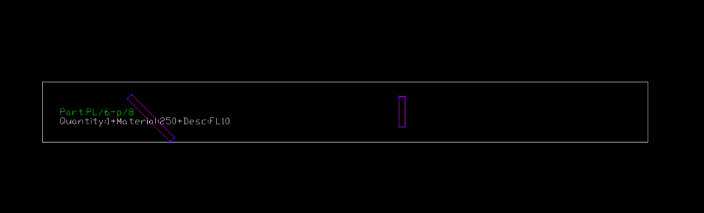
DXF converted output of members with front face weldedDXF converted output of members with back face welded
SETTINGS TO CHANGE FOR EFFICIENT EXPORT
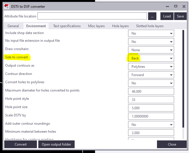
Change “side to convert” under Environment tab as Back in the convertor to create DXF with contour marks at Back view.
Snip from the convertor
For plates if Back option is chosen you get DXF Files converted like below images. So few advanced settings has to be done.
Snip of Plate profile with Back option chosen
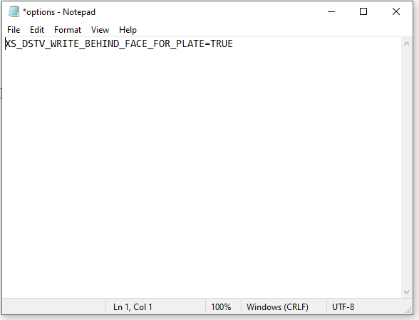
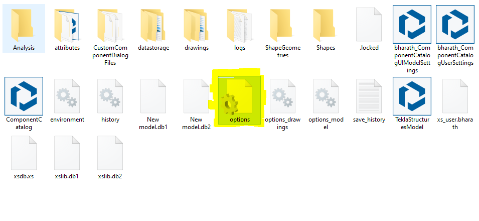
For plates members follow the below steps: 1) Open the model folder 2) Create a new text document 3) Type “XS_DSTV_WRITE_BEHIND_FACE_FOR_PLATE=TRUE“ 4) Save the document as “options.ini“ Refer below snip for Clarity
Snip of NotepadSnip of the File in model folder
Now repeat the conversion the convertor works efficiently providing a quality output.
The key to this is to specify a chamfer value, and at least three points using the PolyBeam class. You must also provide a profile type that Tekla understands – otherwise you’ll get a bunch of straight lines.
Here’s some basic code to get you started:
You should be able to easily import, into Tekla, any curved Beam you want. The principal requirements are: (i) start point, (ii) end point, and (iii) also rotation. Start point and end point and centre point – this will not do: you will also need a third vector if you are going down this route, and I feel that it needlessly complicated. This can be obtained via any any means: CSV files, or directly with Rhino APIs (this might require programming in both Tekla and Rhino).
It is best to control your data source
If you read our past blogs re: CSV files – everything is contingent on how it is obtained. If you have rubbish in, you get rubbish out. We worked extensively with a party on the Westgate Tunnel, who promised .CSV files, but then provided me with corrupt and inaccurate data points, and did not provide the data in the agreed upon format. This makes for headaches and recriminations — and ultimately dissatisfied customers — but what can you do if they provide you with rubbish data that you cannot verify? So if you’re going down the CSV file route — then you need to know how the CSV files are being produced, and that there are not mistakes in them: e.g. missing columns, nonsensical data values, and that they are being produced programmatically etc. or at the very least have excellent lines of communication with your client to resolve these types of issues. Controlling the data source obviates these problems.
Or another problem I faced – you’ve agreed on CSV files, but the format changes each time an update happens. Someone changes the name of a column header – or they give you a file with irrelevant stuff in there. Every time you have to manually edit something, you’re introducing the possibility of errors. All of this can be solved by controlling the data source.
The Devil is in the Details
Again, as with most things, they seem simple at first but the devil is in the details: you gotta tackle the problem of rotation and also profile mapping and weird gotchas in Tekla – that are not documented. Then another important thing to manage:
Revisions and changes
How are you gonna manage this? How are you going to document variation hours? Likely you might have to add IDs to each member. This will have to be incorporated into CSV files from the outset. Or if you have the Rhino model in hand — then you could just see what has been changed programmatically: (i) are they IDs all the same, and (ii) if so, have they been moved. Now this will entail persistence of an old model to be compared with a new model, and a form of documenting these changes. This takes extra time, extra programming, and extra documentation management.
All team leads, trainees must know how to overlay 2d annotations to IFC model and upload to trimble connect.
Please watch this youtube video on it. I am asking Ragul to upload a training model with GA and Assy drawings. What you have to do is follow the video, extrat the dwg and upload the GA and Assy drawing to trimble connect on your private trimble connect.
You may use campus for that. Get Ragul to check and approve.
Ever wondered how to automate the processes in modeling of steel structures, increase efficiency and accuracy. Grasshopper has got all the answers. Grasshopper is a visual programming interface like the Dynamo we saw in the previous blogs. It is built in within the 3D modeling software called Rhino. Tekla has released a link which enables algorithmic modeling for Tekla Structures using Rhino/Grasshopper. Even the toughest and tiresome models can be easily created using the Grasshopper-Tekla Live Link provided you have a strong visualization capacity and good understanding of the underlying geometry.
We have tried using it for our jobs and it provides great flexibility to alter the parameters. One of the job we used for is creating a Spiral stair and the process was pretty easy and we got accurate results. Another challenging job we experimented was the outer framing for cladding panels, along the sides of a bridge which had a tricky geometry. Have a look at these in the following video.
When it comes to 3D modeling, there always exists limitations with conventional modeling software while working with complex structures. In business, it is very important that each and every need of the customer must be fulfilled without compromise. With these things in mind we started experimenting various ways to model complex structures. Dynamo came into help here. The main advantage of using Dynamo is its accuracy and speed.
We have done a aesthetic facade for an atrium using Rectangular hollow steel section which comprise of a Sine wave geometry in its elevation. Without the need of creating each and every piece individually we created a script which automatically generated the facade with the required profile. The final output was really accurate which may be limited when doing it manually. The size and shape of the overall model can also be adjusted easily to our requirements by using Dynamo.
If you want us to model any challenging structure like this, please do contact us.
The DXF format is a CAD data file format developed by Autodesk to allow data interoperability between AutoCAD and other CAD programs.
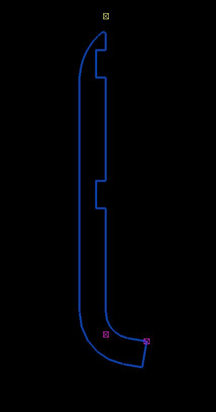
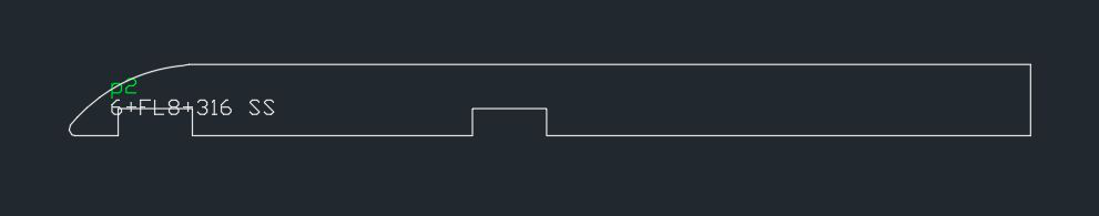
Issue: One issue we faced when using the polybeam comments feature in Tekla is that if we used the feature to add comments on a DXF file imported into Tekla, then the output drawing will render the proper shape.
See the image below for the plate shape.
This won’t work. This is best modelled as a countour plate.
See the below for the DXF output shape. The bending portion will not appear properly.
DXF – this is output. It won’t work with polybeams.
Solution:
Don’t use poly beam comments in Tekla model to the “L” shape plates.
Instead, use the Contour plate comment to make the “L” shape plate in model.