Tekl1 modelers typically create and develop Tekla models close to the model origin (0,0,0) to maintain optimal modelling performance and accuracy. However, when sharing IFC files for coordination, clash detection, or BIM integration, the model may need to be positioned at its actual project location using global Easting and Northing coordinates.
By exporting the model using a Base Point, multiple IFC models from different consultants and contractors can be accurately overlaid within BIM coordination software.
Setting Up a Base Point
To export a Tekla model to global coordinates:
Open File > Project Properties > Base Points.
Create or modify a Base Point.
Enter the required Easting and Northing coordinate values.
Use the Base Point when exporting the IFC model.
When the IFC is exported using this Base Point, the model origin is shifted to the specified Easting and Northing coordinates, allowing the model to be correctly positioned within the global coordinate system.
Using a Specific Model Point as the Base Point
In addition to using the model origin, Tekla allows any point within the model to be selected as the Base Point.
This provides greater flexibility when project coordinates are referenced from a specific grid intersection, column location, survey point, or benchmark. The selected point can then be assigned the required Easting and Northing coordinates during export.
Applying Rotation
The Base Point functionality also allows the model to be rotated relative to the selected reference point. This is particularly useful when the project grid is not aligned with true north or when a specific orientation is required by the client or project team.
By defining both the coordinate location and rotation, the exported IFC can accurately represent the model’s real-world position and orientation.
Demonstration
The video below demonstrates the complete procedure with a practical example, showing how to:
In this blog, we will look at how to create and share new materials in a Tekla model. By default, Tekla comes with a predefined list of materials stored in the system drive (C drive). However, in many projects, we often need to add custom materials based on project requirements. To add a new material, go to the Menu at the top left corner, navigate to Catalogs, and then open the Material Catalog. From there, select an existing material, right click & selct “Add Grade,” rename it as required, and assign the appropriate density. Once saved, the new material will be available in the model.
When sharing the model, especially using the db1 file to reduce file size, the newly added materials may not be available to the recipient. This is because custom materials are stored separately. To ensure the other user can access the same materials, you need to share the file named “matdb.bin” from the model folder. This file is created only when new materials are added and must be included along with the db1 file.
Alternatively, there is another method to share materials. In the Material Catalog, you can use the “Export” option available at the bottom to save the material data as a separate file. This file can then be shared, and the recipient can import it into their Material Catalog to access the same materials.
Watch the video below for a step-by-step demonstration of this process.
Cloning of Assembly Drawings in Tekla is the Smartest Way to Improve Detailing Efficiency
In structural steel detailing, efficiency and accuracy are critical to delivering projects on time. As projects grow larger and more complex, detailers must find smarter ways to manage repetitive components and maintain consistency across drawings. One powerful feature that helps achieve this in Tekla Structures is Assembly Drawing Cloning.
Cloning assembly drawings is a highly effective method that allows detailers to duplicate an existing assembly drawing and apply it to similar assemblies within the model. Instead of creating drawings from scratch every time, detailers can reuse a well-configured drawing layout, saving significant time while maintaining uniform standards across the project.
In steel structures, many assemblies such as beams, columns, bracing members, and connection components often share similar configurations. When these assemblies are modeled with comparable geometry and detailing requirements, cloning becomes an invaluable tool. By copying an existing drawing and adapting it automatically to another assembly, Tekla helps detailers maintain consistency in dimensions, views, marks, and annotations.
Another advantage of cloning is its ability to intelligently adapt to small variations between assemblies. Tekla automatically adjusts views, dimensions, and annotations to match the geometry of the new assembly. This allows detailers to reuse drawings even when there are minor differences in member length, hole positions, or connection details
Please refer to the video below, which elaborates on the cloning process and the working method in Tekla Structures
When the model is amended after issuing the first set of drawings, the affected assembly drawings will appear as “Parts Modified” after numbering is completed. While updating such drawings, certain considerations are important to ensure effective and quick detailing.
1. Freeze Option
When Freeze is OFF, Tekla automatically updates dimensions according to the movement of parts. While this may seem convenient, the decision to turn Freeze ON or OFF depends on the nature of the amendment.
If no new members are added to the assembly and only existing parts are moved, it is recommended to keep Freeze OFF, as Tekla will correctly update the dimensions.
If new parts are added to the assembly and Freeze is turned OFF, Tekla will automatically generate additional dimensions for the new members and may also alter existing dimensions. This can result in extra work to restore the original dimensioning arrangement.
Guideline:
When no new parts are added, turn Freeze OFF.
When new parts are added, turn Freeze ON.
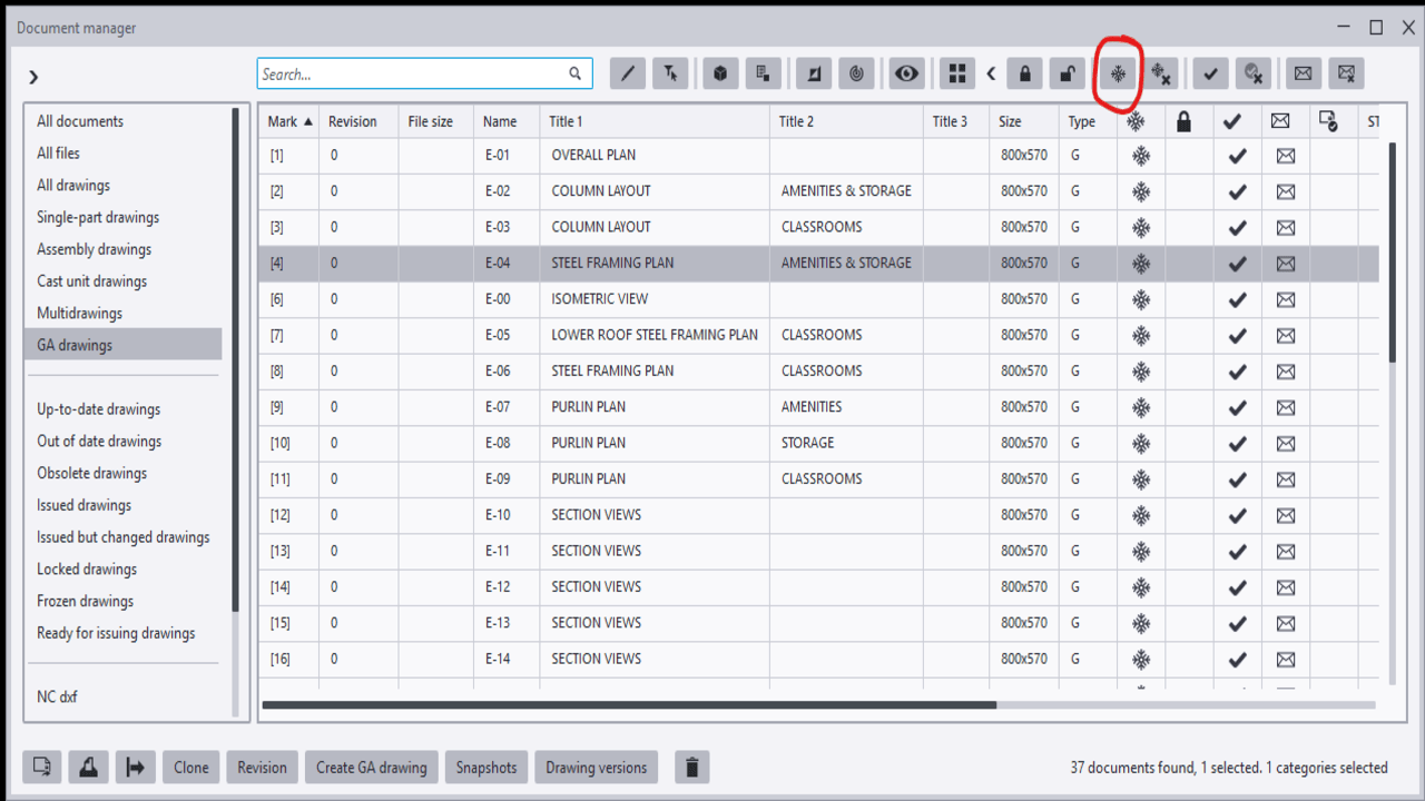
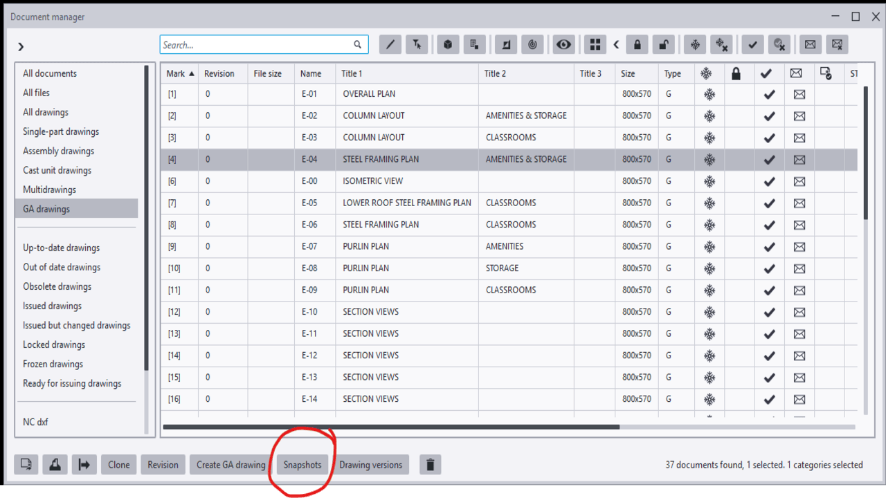
2. Snapshot Option
Among the drawings marked as “Parts Modified,” not all drawings necessarily contain actual changes. Some assembly drawings may appear as modified because they share common connection components with other assemblies that were amended.
In such cases, the drawing may not have any visible changes and may only require an open-and-close action. However, there is a risk that certain dimensions may be automatically deleted or altered by Tekla during the update.
To avoid missing dimensions or unintended changes, the Snapshot option is highly useful. It allows detailers to compare the drawing before and after the update. By reviewing the differences, any unnecessary or unintended modifications can be identified and corrected, thereby minimizing the risk of errors.