For instance, when we intend to include this cloud and text markup in all drawings, our current process involves adding a cloud followed by a text box. However, this repetitive action for each drawing proves to be extremely time-consuming. So, I’m going to share a trick with you (which Tekla already has) as an alternative solution.
What to do:
* First, you need to create a markup exactly how you want it.
* Next, select the elements that you want to be included in the markup. Be careful when selecting, as even a line that is selected will be included.
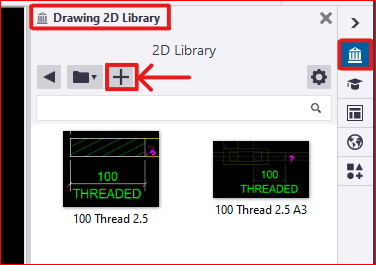
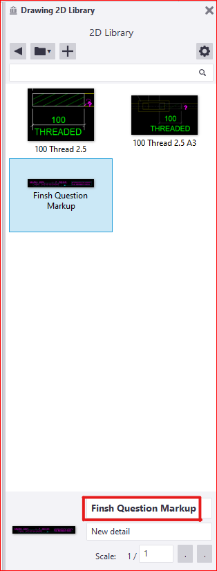
* In the Tekla drawing workspace, you’ll find the ‘2D Library’ option. Open it and to add a new detail, click the plus icon
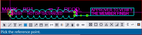
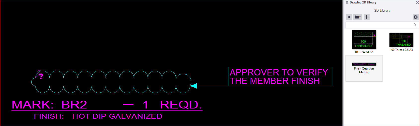
* Next, you need to select a reference point near the markup. This reference point will serve as the future insertion point for your detail in every drawing
* The next step is to select an area that will serve as your reference image, appearing like a thumbnail. after that the detail will be created and the the library looks like this
* There are others options available to edit these existing details as well. Feel free to explore these options; you won’t need additional tips for that
* Finally, if you wish to insert this into another drawing, you just need to select and pick the insertion point in your drawing. The chosen detail insertion point will determine its placement. ( for example, I chose a location where I didn’t want the detail to appear.. 🙂 )
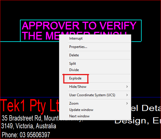
* You can select and then right-click the mouse to choose the “explode” option, allowing you to select each individual element within the detail markup
* We have additional blog posts that explain various tips and tricks in Tekla. Feel free to explore those resources as well
* If you have any doubts you can mail to koshy@tek1.co.au
Normally in Tekla, if we want to copy objects or components from one object to another, we have to follow these steps :
Select the objects and components you want to copy.
Execute the “Copy to Another Object” command.
Choose the source object.
Select the destination object.
The objects will be copied by reference, aligning their coordination system with that of the source object to the destination object’s coordination system.
Please note that the coordination system is used to ensure the accurate positioning of the copied objects in relation to the source and destination objects.
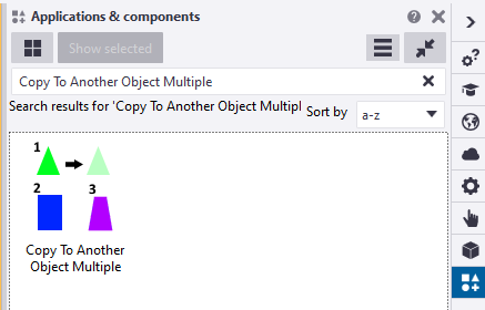
Macro: Copy to another object multiple
The command “Copy to Another Object” poses an issue when used in Tekla. It does not allow the selection of multiple destination objects at once; instead, we can only choose them one by one. This limitation can be time-consuming, particularly when working on large projects.
Tekla offers a macro called “Copy to Another Object Multiple” that fulfills the requirement of selecting multiple destination objects. This macro functions similarly to the command mentioned earlier. First, we need to select the objects before running the macro. Once the macro is executed, it prompts us to select an object. Then, we select one source part, after which we can conveniently use drag selection to choose multiple destination objects. Finally, press the mouse middle button.
the snapshot was taken on Tekla version 2022
You can find this macro in the Applications & Components catalog of Tekla Structures.
Introducing a New Approach: The Modified Implementation for Copying Objects in Tekla
The ‘Copy to Another Object‘ command works by copying objects in relation to the source object and pasting them according to the destination objects
The coordination system plays a crucial role in defining the position and rotation of a part in Tekla
It is primarily based on the start handle of the part
Altering the coordination system of a part is not possible
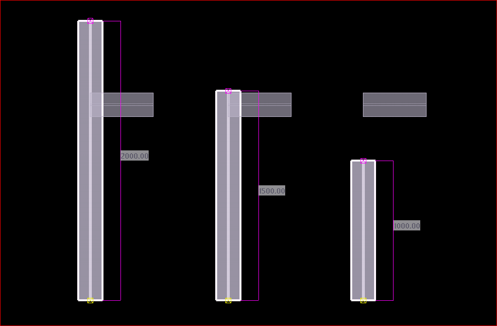
If the destination object’s lengths differ from the source object, a problem arises where the objects are positioned based on the start point
After copying the small beam to other destination objects of varying lengths
In many situations, we often find ourselves having to manually utilize the ‘Copy Linear’ or ‘Move Linear’ commands to perform copying tasks.
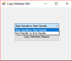
We utilized the Tekla API to Create a new macro that helps to copy objects in relation to the end handle of the part. When executing this macro, it prompts the user to select the desired handling method for copying objects
This is the dialog box that appears while running the modified “Copy Multiple Tek1” macro.
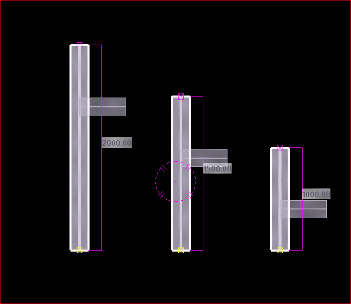
When the “End Handle to End Handle Copy” option is selected, the operation produces an outcome that is similar to the image shown.
members of the Tek1 organization can download the tsep installer file of the above macro by clicking the download button
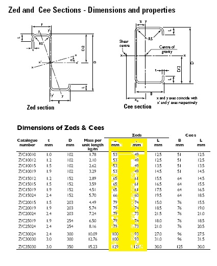
Lysaght Zed sections feature one broad & one narrow flange, sized so that two sections of the same size fit together snugly, making them suitable for lapping. The table below from the lysaght catalogue clearly shows the difference in sizes of each flanges.
Lysaght Zed Purlin Catalogue
The purlin bolts are always placed equidistant from the centre & hence the steel modeller does not have to worry about whether the broad flange of a purlin comes at top or the narrow flange. The broad & narrow flanges will be placed alternatively at the site. This is the case for almost all the times.
But very rarely, there might be additional bolts/holes at the top flange or bottom flange and the steel modeller has to consider modelling the purlins with their exact orientation i.e, whether broad flange of a purlins comes at top or the narrow flange.
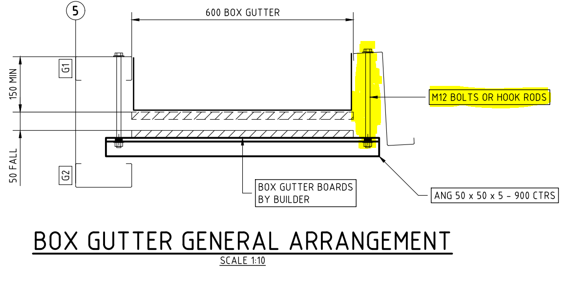
For instance, the below design demands for M12 bolts or hook rods from the top flange of the Zed purlin to support the nearby gutter. Hence the modelling has to be precise about the broad flange & narrow flange for each purlin in a continuous row.
This blog illustrates how to provide the dimension detail in an efficient way for sheet metal bending using Tekla Structure. For bending of sheet metal, we need to provide add-on information in Pdf drawings and dxf files for calrity of fabricator.
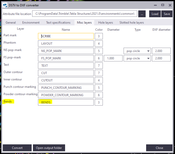
By default the Tekla Structures can generate drawing with bend lines. But it is not sufficient for the fabricator, until he knows which side to bend the sheet. This can be achived using the plugin “DSTV TO DXF CONVERTER” available on Tekla Warehouse. (Note: Always check if the drawings are created in front view for high quality output.). See below image for clarity
Snap without bending informationon pdf drawingsSnap with bending informationon pdf drawings
Steps to show bending lines: When a DXF file is exported using Tekla it shows reference line. In order to add the bending lines we use the tool “DSTV TO DXF CONVERTER“.In this tool, there is an option to provide a bending line in a different layer on the dxf file. The output dxf files contain information in which direction the sheet has to be bent. This information can be used by the detailer and fabricator for quality output. See below image for clarity
DSTV TO DXF CONVERTER TOOLSnap without Bending information on dxf filesSnap with Bending information on dxf files
The following codifies our processes. It is made for the following reasons:
(i) to educate our own staff, about what they need to know and secondly,
(ii) to make transparent to our clients, how we operate. We are essentially inviting you into our kitchen, so you can see for yourselves how we cook, and to then decide, whether you would like to dine with us.
Mistakes are expensive. (Why this is the case?)
Understanding risk and liability.
Understanding risk: liquidated damages, contractual obligations, insurance. Understanding the legal system in Australia, USA, UK.
e.g. to NEVER issue drawings for construction without consultant approvals.
Confirm important details in writing. (Why is this the case?)
Understanding: the importance of accurate estimation(s) of deliveries (Why is this the case?)
What do clients value?
To make things as easy as possible for the client, and to make the client money. This might involve:
Quick drawings.
Accurate drawings.
Timely feedback (i.e. what is the status of their project?)
Pushing the job along.
Solving problems with minimal noise
If they client asks for something, we need to either: (i) deliver what they ask exactly, or (ii) give clear reasons why it can’t be delivered. If the client asks for an program schedule, it will not do to say: “yes sir” and completely forget what the client asked for.
Delivering on your promise. If you say “5 minutes” then deliver in extra 300 seconds, and not, 6 hours later. (Why is this important? (the client might allocate an entire team to fabricate something in 5 minutes, and you will cost the client $10,000s of dollars if they are sitting around in the factory floor, without nothing to fabricate, because you didn’t deliver the drawings when promised)).
Making things easy for the client to fabricate and/or manage their projects.
Good grammar, good English, and clear communication.
Extra material: to be immediately communicated to the client. (Why? So clients can recover their costs).
Tender drawings vs for construction drawings to be compared and the differences reported to the client in a report. (Why? So the client can recover costs).
Here is a sample of bridging list we provide with Take off. We provide the length and the quantity for accurate estimation. The model also shows the bridging.
How to achieve 800 tons per month Capacity with small efficient teams
Tekla provides a few tools for experts users. Careful study of model, diligence and discipline in placing members, Set up of template model makes it possible to use these tools with maximum efficiency.
Custom Connections
Auto Connections
Customized Drawing templates.
Manner in which Members are placed.
Macros which work between Autocad and Tekla
Customized Checking tools
These are the tools which will increase productivity with expertise.
These tools are good only with people who have a lot of experience, and who have access to our in house developed API tools for Autocad and Tekla.
Our clients will get the full advantage when they use us for detailing