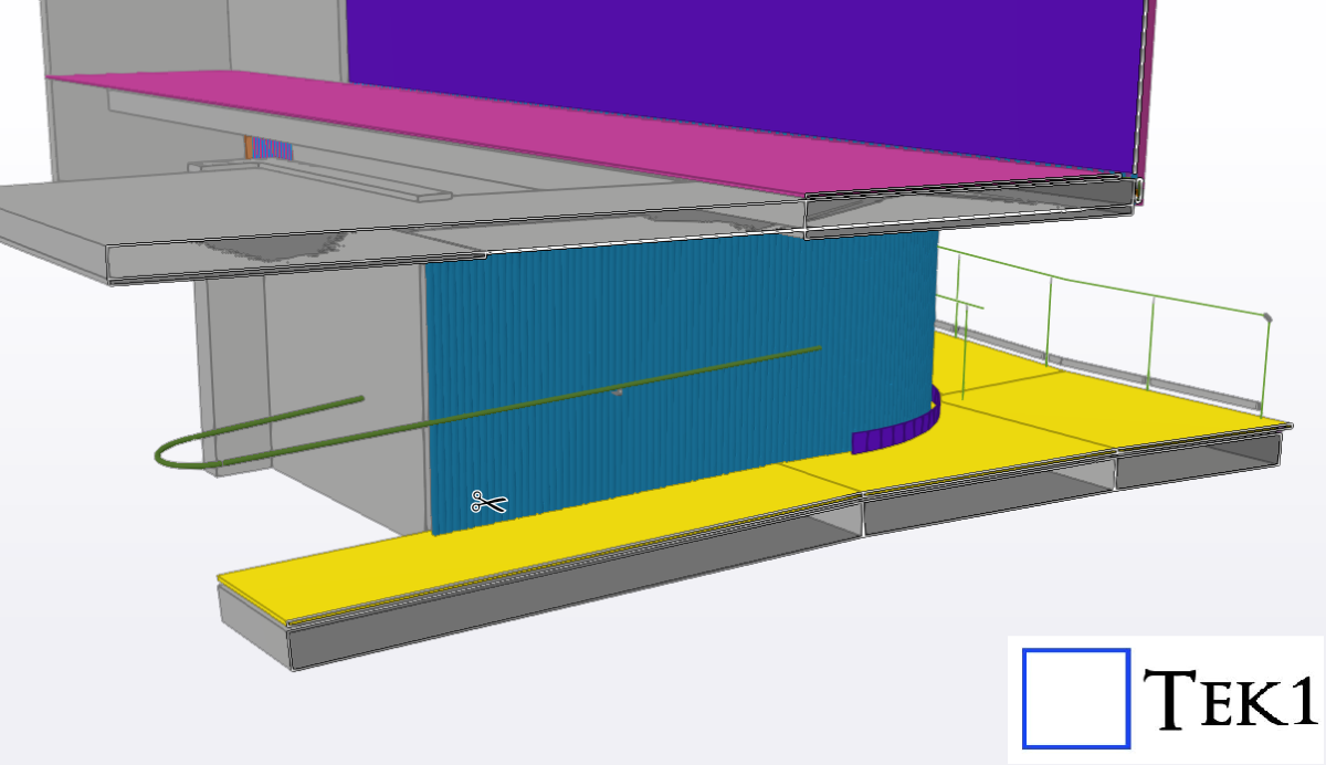
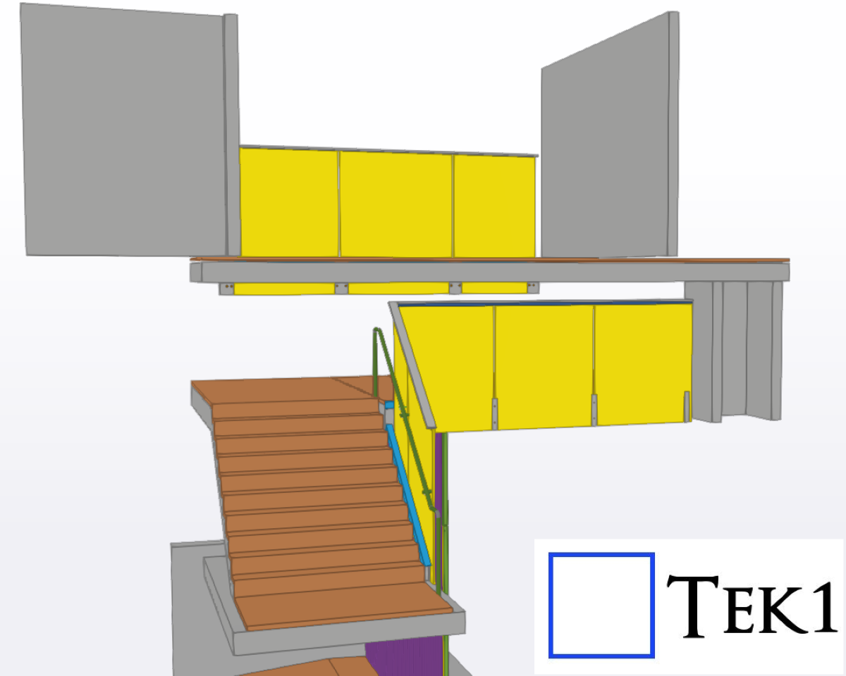
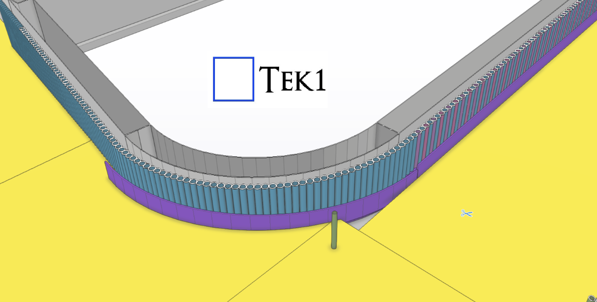
TEK1 completed a cladding project for a prominent organization in Australia. The goal was to provide claddings to buildings for aesthetic purposes. Apart from that, the client also wants us to detail handrails & glass balustrades for the stairs.
This page show cases some of the Steel Detailing projectgs completed in Melbourne, Sydney, WA, Brisbane Tek1 has completed
TEK1 completed a cladding project for a prominent organization in Australia. The goal was to provide claddings to buildings for aesthetic purposes. Apart from that, the client also wants us to detail handrails & glass balustrades for the stairs.
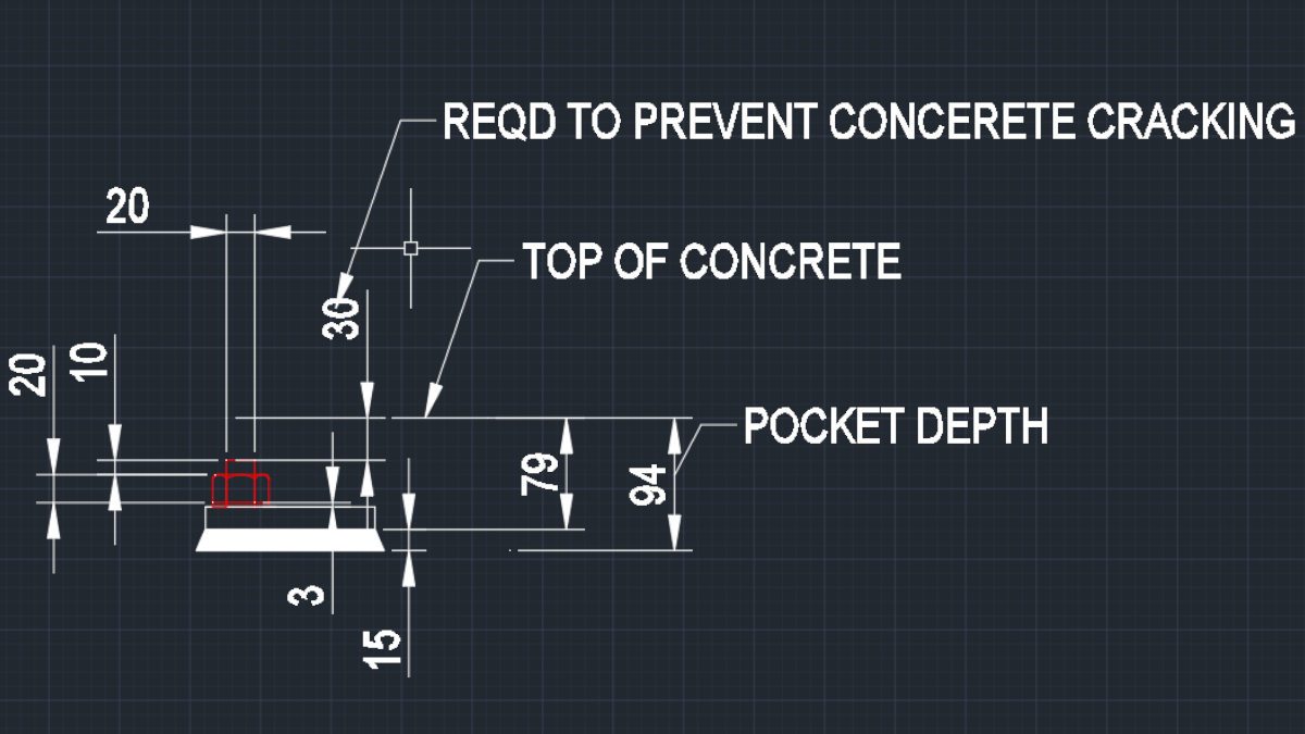
The minimum washer size is 3 mm. This could be different. If nothing is mentioned use 3 mm.
The minimum bolt stick out should be 1 pitch. For M20 it is 2.5 mm. Use 10 mm stick out.
Also there is grout. Pockets when cast could be of different depths. Use design grout of 15 mm minimum.
The top of the bolt should be 35 mm below slab level to prevent concrete Cracking.
Hence to be practical use 100 mm pocket depth with a base plate thickness of 16 mm and bolt size of 20 mm.
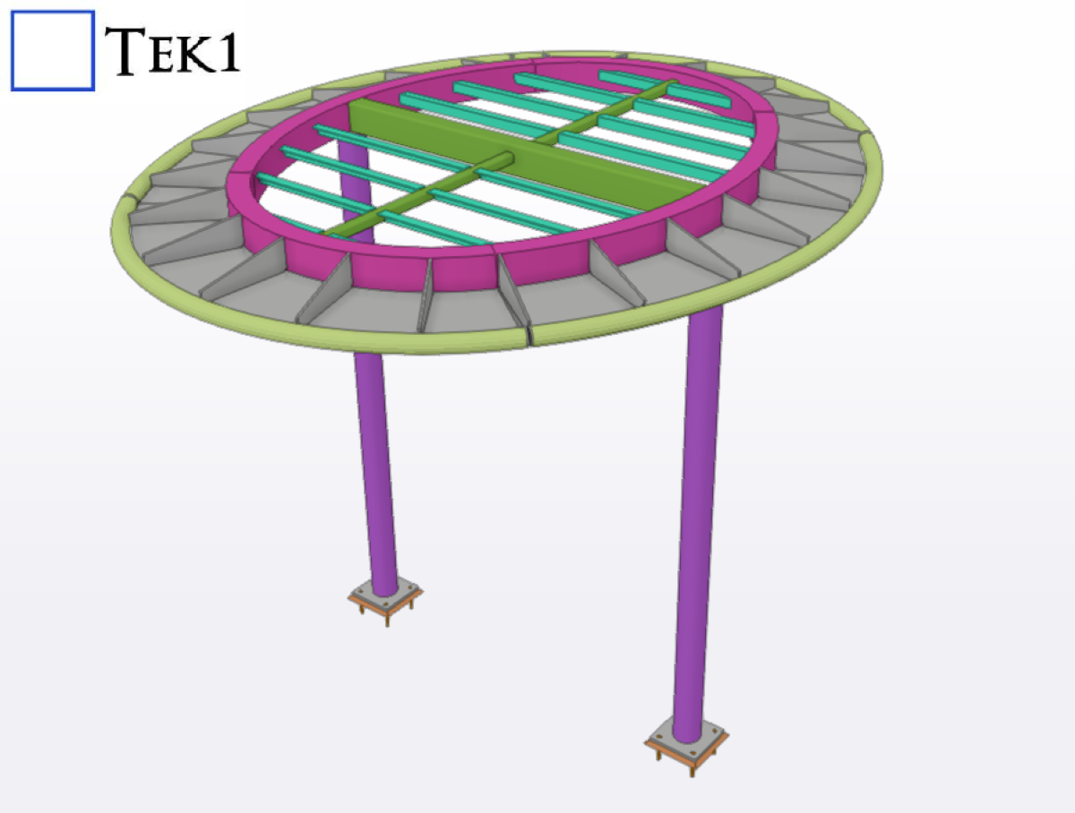
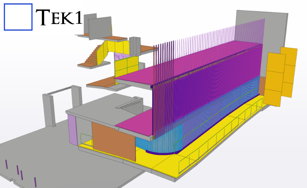
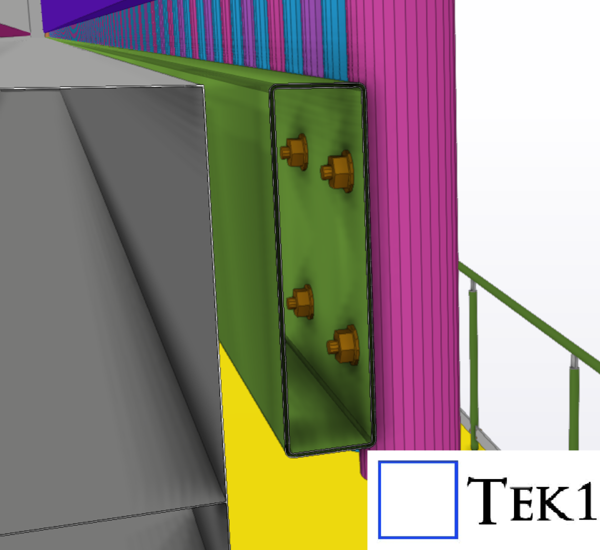
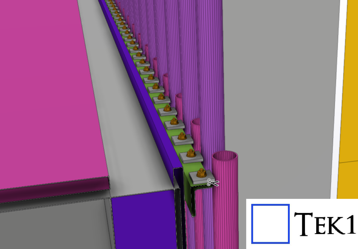
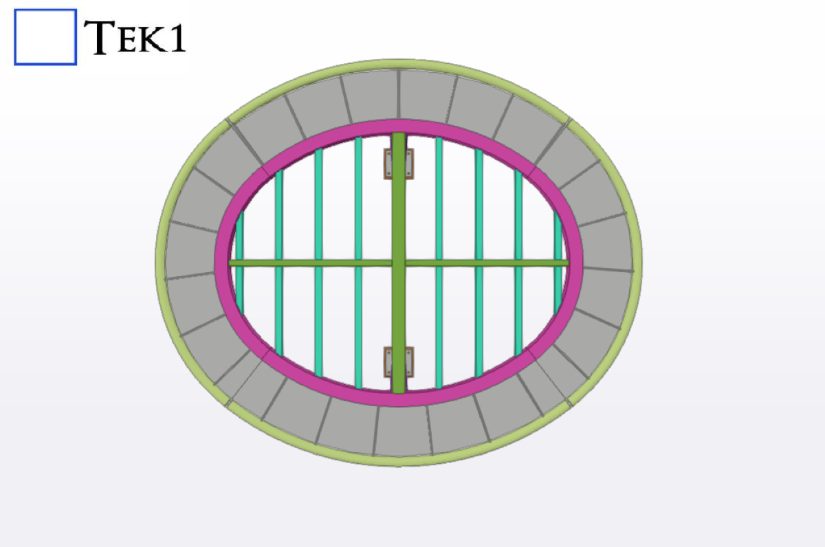
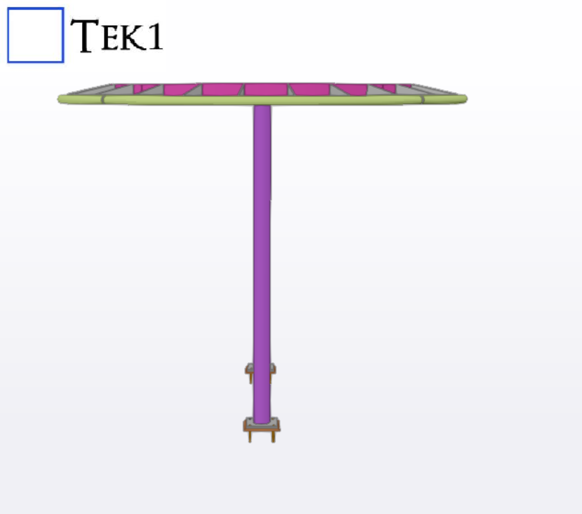
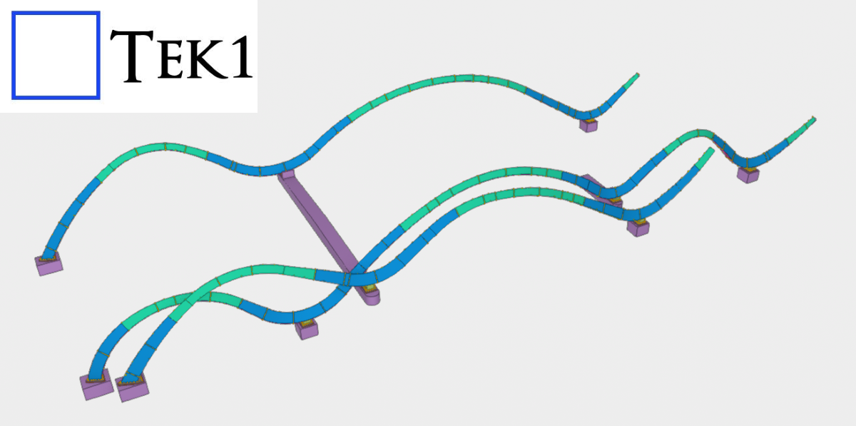
TEK1 completed a canopy project for a prominent organization in Australia. The goal was to provide detailed support for steelwork canopies.
Meticulous Care – Expertise alone not sufficent With many many changes, Mulitple site meaures, point cloud data, unless the processes are good and the care is meticulous, the knowledge and expertise will not count Street Address ATL Station State NSW Country Australia Modeler Ganesh Kumar
With many many changes, Mulitple site meaures, point cloud data, unless the processes are good and the care is meticulous, the knowledge and expertise will not count
| Street Address | ATL Station |
| State | NSW |
| Country | Australia |
| Modeler | Ganesh Kumar |
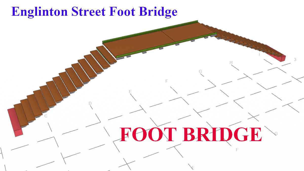
Recently, we were awarded a project to detail a curved section on the bridge for a reputed organization in Australia. The geometry involved presented some unique challenges.
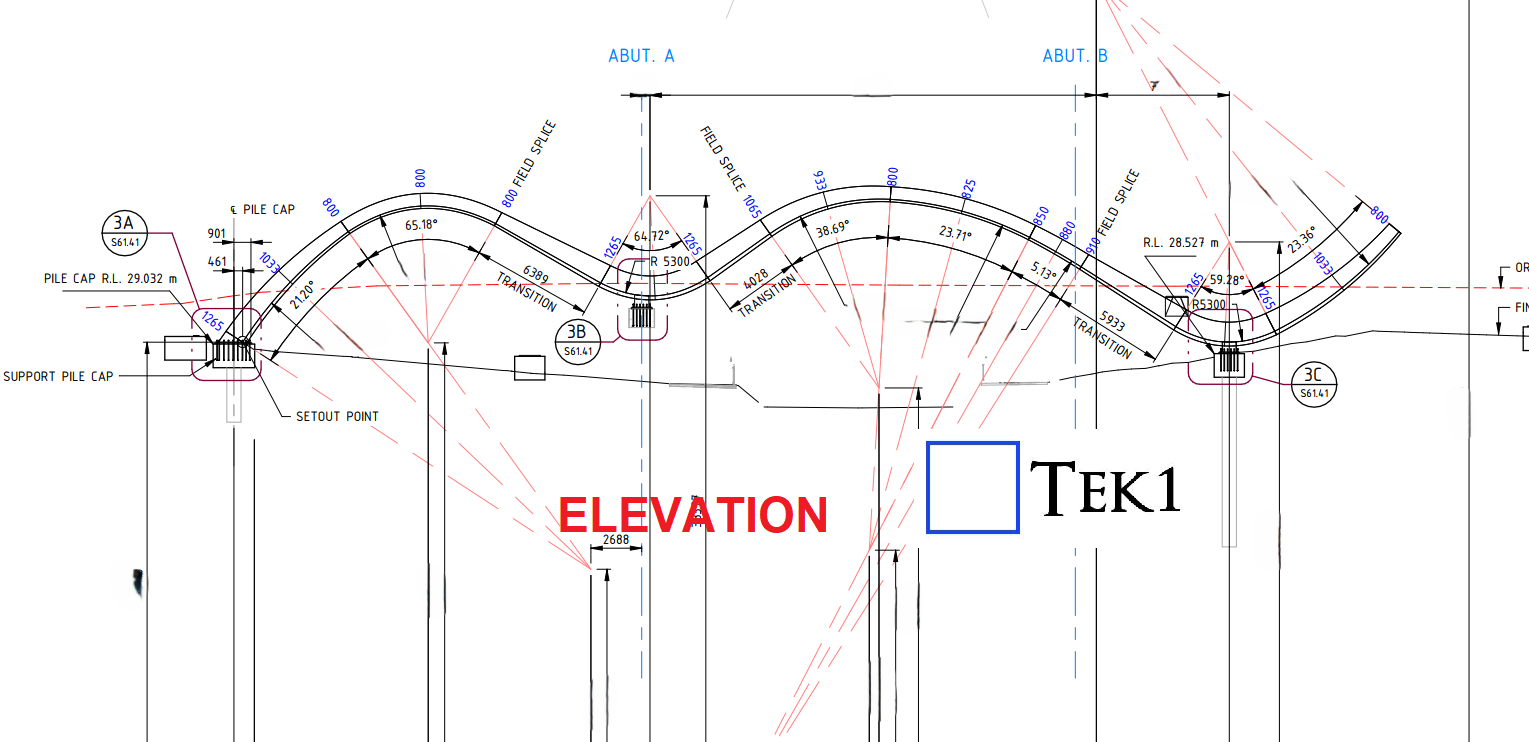
From the elevation, the structure followed a non-linear zig-zag curvature, creating a dynamic and aesthetically driven form.
(more…)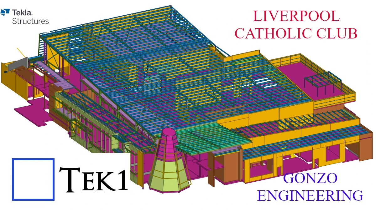

Upload the reference models when you upload the model to trimble connect.
Now any one can make some quick checks.
You can turn off/on the reference models for quick checks.
May adjust the transparency too
#Trimble Connect #Tekla
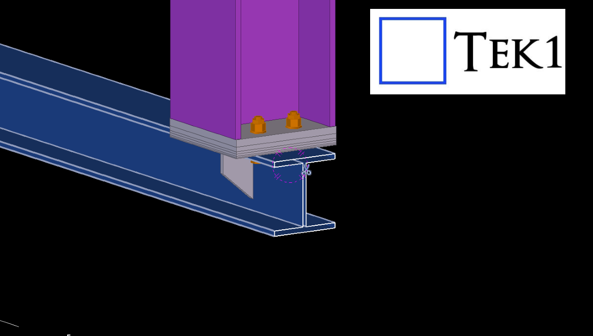
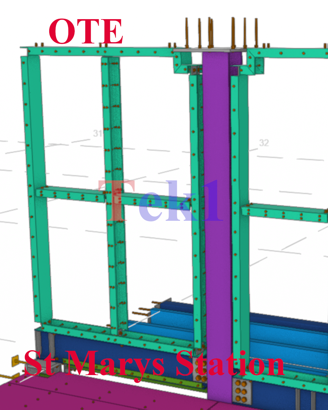
In this blog, we share a proposal we made to the builder to make installation easier on-site.
In the OTE platform steel, we provided a PSD beam (OTB5) to support the platform screen doors below. These beams will later need to coordinate with the door manufacturer’s system.
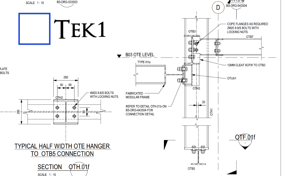
However, in practice, structural steel is rarely placed in the exact designed level due to factors like concrete alignment, mill tolerances, and site conditions. If the beam is installed as per the design without adjustment options, it may not match the required level for the doors.
To solve this, we proposed adding packer plates so the PSD beam level can be adjusted during installation.
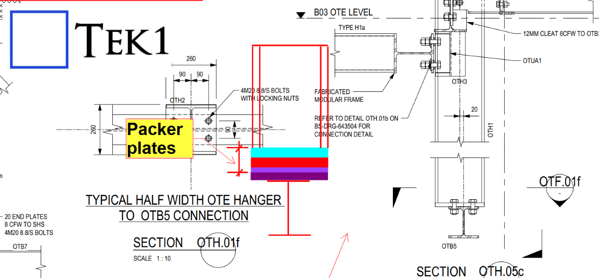
The client accepted our proposal, and this solution will make the erection and alignment process much easier on site.