Category: Steel Detailing Blog

This page show cases some of the Steel Detailing projectgs completed in Melbourne, Sydney, WA, Brisbane Tek1 has completed

  • EFFICIENT DSTV TO DXF CONVERSION

    Contour Marking: It is an information written in an NC file that passes information to the NC machine on the layout and the parts that are welded together.

    Requested from client

    Tek1 do care about every client so we thought of seeking the help of Trimble Connect warehouse and found an plugin suiting the criteria.

    Convertor plugin found on Warehouse

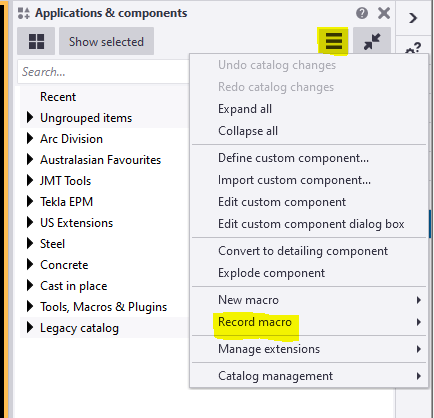
    How the Convertor Works

    The convertor converts all the NC files to DXF. By default it converts the members in Front View. To obtain the contour marks that are available at the back face few changes had to be done on the convertor setting for efficient changes.

    DXF converted output of members with front face welded
    DXF converted output of members with back face welded

    SETTINGS TO CHANGE FOR EFFICIENT EXPORT

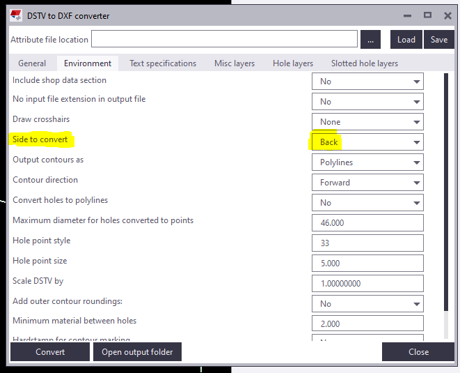
    Change “side to convert” under Environment tab as Back in the convertor to create DXF with contour marks at Back view.

    Snip from the convertor

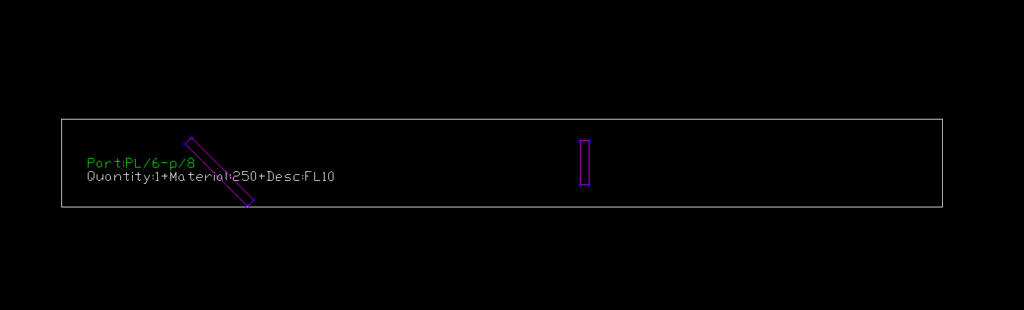
    For plates if Back option is chosen you get DXF Files converted like below images. So few advanced settings has to be done.

    Snip of Plate profile with Back option chosen

    For plates members follow the below steps:
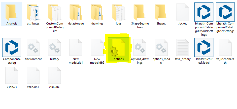
    1) Open the model folder
    2) Create a new text document
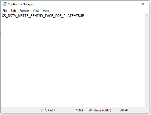
    3) Type “XS_DSTV_WRITE_BEHIND_FACE_FOR_PLATE=TRUE
    4) Save the document as “options.ini
    Refer below snip for Clarity

    Snip of Notepad
    Snip of the File in model folder

    Now repeat the conversion the convertor works efficiently providing a quality output.

    Refer Tekla Structure support link for detailed explanation of the convertor settings.
    DSTV to DXF Converter | Tekla User Assistance

    Bharath Nagarajan – Blogger
    Tek1 Pvt Ltd

  • Bolt to be used in Glazing location

    Bolt to be used in Glazing location

    Author: Pon Dhileepan

    While working in a project called Bateman Bay, TEK1 came across a situation where PFC members are provided to support glazing. PFCs are laid flat, a 50mm U channel is run along the PFC which supports the glass. The below image is the cross section across the glazing and it elucidate the set up.

    This image has an empty alt attribute; its file name is image-1.png

    Problem 1:

    These PFCs are connected to columns by 10mm end plate & 16dia 8.8s bolts. The problem arose here as the bolt head of 8.8s bolt would clash with the glass. Refer below image for clarity.

    Hence, TEK1 raised a query as to whether they can cut the glass where ever bolts clash or use CSK bolts. The structural engineer changed the 8.8s bolts to CSK bolts.

    Problem 2:

    Another problem came as the PFC web is just 4mm whereas the CSK head is 8mm. The bolt head will still clashes with glass.

    Then we proposed to weld an 8mm plate under the PFC and CSK drill is to be made together. The proposal is accepted. The below images show that the glazing runs without any hinderance.

    TEK1 detected the issue earlier which saved cost in cutting the glass at site. Structural engineer often do not consider these kind of clashes and it is the duty of the modeler to find this out and make this to structural engineer’s knowledge.

    Thanks for reading.

  • Estimation / Take off Tools

    We’ve created many libraries that handle estimation. Here are some examples which you may view or use as the case may be.

    Apologies folks, this is documentation for our own staff. If you’re not on staff, I’m afraid your access will be limited. Videos are located in the documentation contained in the Drive Folders. Please carefully read the documentation and watch any videos if required.

    Advanced Steel Member Placement:

    Draw some lines in AutoCAD or Advanced Steel. Set up a CSV file that maps lines to Advanced Steel Beams. Run the command in Advanced Steel, and Advanced Steel beams are produced.

    Advance Steel – ConvertToBeams (CTB) Command from Tek1 on Vimeo.

    MemberPlacement tool (AutoCAD):

    Draw lines that come up as 3d lines with a Tekla like interface, which using interop delivers them straight to Tekla:

    Line Based Take-Offs

    • Draw lines and an Excel Spreadsheet is produced showing total lengths and counts for certain steel types. Dlls are located here.

    Take Off Tools

  • Tekla Tutorials For Beginners

    Core Competencies T1 & T2 – colored

    Tekla Skills

    See Video Tutorails Below: (I prefer Vimeo because you don’t have to deal with insufferable ads)

    Youtube Playlist.

    1. Tekla UI: Youtube: (English) (Tamil) / Vimeo: (English) (Tamil)
    2. Columns: YouTube : (English) (Tamil) / Vimeo : (English) (Tamil)
    3. Beams Part 1 : Youtube (English) (Tamil) / Vimeo: (English) (Tamil)
    4. Beams Part 2 : Youtube (English) (Tamil) / Vimeo: (English) (Tamil)
    5. Plate : Youtube (English) (Tamil) / Vimeo: (English) (Tamil)
    6. Bolt : Youtube (English) (Tamil) / Vimeo: (English) (Tamil)
    7. Weld : Youtube (English) (Tamil) / Vimeo: (English) (Tamil)
    8. Concrete member
    9. Column :Youtube (English) (Tamil) /Vimeo: (English) (Tamil)
    10. Beams :
    11. Slab :Vimeo:(Tamil)
    12. Panel :Vimeo:(Tamil)
    13. Footing :
    14. Edit Ribbon :
    15. Grids : YouTube : (English) (Tamil) / Vimeo : (English) (Tamil)
    16. Cut/Fit/Split/Combine :
    17. Chamfer :
    18. Compare members :
    19. Measure :
    20. Points :
    21. Construction object :
    22. View Ribbon
    23. New View/ View list/ Saving view :
    24. Work Area/ Clip plane :
    25. Work plane :
    26. Representation :
    27. View properties :
    28. Screenshot/ Fly/ Rendering :

    Sample Project files :

    Solution for the project files :

    Please find Vimeo link of tutorial videos : Tekla Tutorial For Beginners


    Other Skills:

    • Improve your english: If you’re English skills are weak, then you need to improve it. Don’t “practice your mistakes”. The easiest way to improve is by shadowing. Spend 1 hours a day for a few months – your career will massively benefit as a result of this. Why should I bother learning English? (1) To avoid miscommunication, (2) Clients HATE bad grammar, (3) you will be rewarded financially in your career (clients will prefer you).
    • Learn how to dimension properly.


    The following are tutorials done by Koshy:

    1. Tekla Introduction
  • RFI for additional support members required

    Does a detailer care about supporting the elements which are not available in the structural design, but it could affect the structure? You should care!

    See the below incident for an example.

    STRUCTURAL PLAN

    This structural plan has sections 1 & 2. Refer below snip for section views.

    STRUCTURAL SECTION VIEWS
    DETAIL-A WITH PARAPET SUPPORT

    If you see the above snap, Section 2 has detail-A, which shows parapet wall support. But section-1 does not have it.

    Is that means there is no support required?

    Actually, there is also support required.

    Refer below architect plan.


    ARCHITECTURAL PLAN

    We have noticed that the parapet coming all around the roof (Highlighted in Pink Colour). So we raise RFI regarding this issue for taking it to their attention. Refer below snip.

    RFI RAISED BY TEK1 REGARDING PARAPET SUPPORT

    The client realises the situation and approves providing parapet support members all around the roof. Refer below snip for the client’s response.

    RESPONSE FROM THE CLIENT

    We always keep our client’s out of trouble from these types of issues.

  • Custom Macro to Select Bolt Summary on Selected Assemblies-

    This blog is about the efficient use of using custom macro in Tekla Structures. Tedious or repetitive commands in a model could be time consuming. These repetitive commands can be automated by use of custom macro

    Understanding the bolt parts:

    In Tekla Structure the bolts can be created as single or in a group.
    Bolts are created with two parts joined together. We could consider as Primary Part (Part to bolt to) and Secondary Part (Part to be bolted).

    In Tekla Structures the bolts are released along with secondary parts

    ie. When Bolt Summary is taken, the bolt connected to secondary parts are extracted and displayed on the list.

    Recording the macro to extract the bolt summary:

    To record the macro. Click on the Application button.

    Then click on the access advance feature button and click record macro.

    You could choose either global or local to save the macros and define a name to the macro. Here we have named as Bolt summary for selected Assembly.

    Now the macro will start recoding.

    Follow the below steps to create the macro.

    Step 1: Press Ctrl+B for Reports List to appear.

    Step 2: Click on the required reports to be generated for the selected Assemblies.

    Step 3: Click Create from selected button.

    Step 4: Finally Stop the recording.

    Now Checking the custom macro created:

    1: Select an assembly for which bolt reports has to be taken.

    2: Double click on the custom macro to perform the task.

    The bolt summary for the Assembly is generated.

    Using the custom Macro we could define all the tedious and repetitive works in a custom macro and use to save time and man-work involved.

    Note:
    Incase the macro has been recorded with error. You could delete the custom macro created by right clicking the created macro and choose delete option.

    For creating API on “How to programmatically create bolt list reports from selected model objects”

    https://www.tek1.com.au/how-to-programmatically-create-bolt-list-reports-from-selected-model-objects-tekla-open-api

  • STEEL MODELER ATTENTION – DEALING WITH CAMBER

    TEK1 worked in a railway foot over bridge with 2 lifts, 2 ramps, 2 stairs connecting platform and overpass, a canopy and 7 platform stairs. The main challenge is the over pass. As per design, the steel truss after erection must be cambered to different millimeters at different intervals. There were two terms “Residual camber” and “Reference Profile” in the structural drawing. Many do not that what these mean. Any misunderstanding about these terms would result in redoing the entire overpass. But TEK1 had good understanding of these terms and avoided heavy rework.

    This blog is to educate the modelers regarding residual camber and reference profile. Kindly refer the camber diagram below.


    The residual camber at the south end is 67mm and reference profile at the same end is 62mm. Residual camber is the camber value which must be given in the steel assembly drawings which the steel detailer supply. Whereas reference profile is the camber value which the structure attains after applying all the dead loads. Here the dead loads are concrete load and self weight of the steel.

    Hope this helps you. Thanks for reading.
    Ramakrishnan.L
    TEK1.

  • Monash Freeway Gantry

    There is a large number free way gantries across melbourne. Tek1 has detailed a good number of them very efficiently.

    Here is an example of one such Gantry we have detailed for our Melbourne client in the SouthEast.

    There are couple of types of gantries, very similar. The large span gantries have to be fabricated with a camber which is challange for the detailer and fabricator.

    Managing weld distortion, transport etc are the challenges the fabricator will have solve.

    Most of such jobs come with a very short delivery time between order and install, and generally high pressure jobs. Getting first time right is super important.

    https://youtu.be/Kw84sf-bllg